A couple of videos back some feedback on my YT channel requested info on post production of video and audio to remove annoying background "white" noise such as fans etc from my vids.
The resulting explanation only went for a few minutes so for this video I have also stuck on some info about the puppy cam project which is an old Raspberry Pi 3B+ running some video software that lets me look at the puppies when we're out of the house.
The project has been fine so far, but I needed to "widen" the field of view and as well make the bodged 5V fan adjustable in a "crudimentary" way.
I have it in mind that I can extend the WiFi coverage at home into the paddocks (~100m), chicken yard (20m), front gate (80m), greenhouse (10m), dog yard (6m), goat/sheep paddock (70m), etc., etc., but I don't want to wire up power to supply extender units.
I've been wondering if solar power is a viable option. Certainly there are a few projects on the InterWebs that seem to suggest it might be possible.
I've started looking at ESP8266 options, but also lately have been more interested in ESP32s with their low current sleeping ability and WebServer possibilities (e.g. setting hours for operation, monitoring traffic, etc).
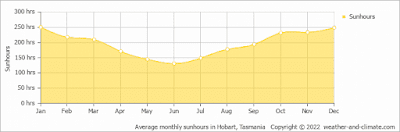
We don't get that much solar down here in Tassie, so whatever set up is implemented needs to be efficient if I'm going to succeed with a solar powered option.
To that end I've been trying out some different solar panels arriving in the mailbag in terms of voltage, current (hence power) and it came to pass that one boring day I exceeded the design specs on a solar panel tester.
Ridiculous as you will see in the video! Once I've decided on the solar panel I'll switch to the power delivery and control systems. Interesting project, with a few more installments to come - watch this space.
The flow of orders into the mailbag has slowed considerably, due to many factors.
Certainly the need has dropped off as the buckets are brimming with project fodder, and as well the cost of both new items and their freight is becoming prohibitive for a humble home hobbyist.
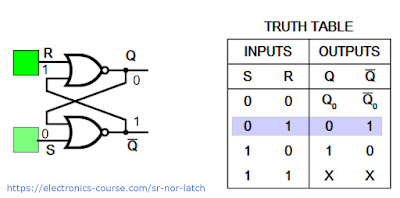
In an earlier blog and video I was messing around with a fundamental element of computers, the Set/Reset Latch (S/R Latch), built around a CD4001 quad NOR gate. It's great, but evolution of this circuit has led to another element known as the S/R flip flop.
SR Latch
SR Flip Flop
There is SO MUCH information out there about these logic circuits, but I'll just recommend two sources if you are the type that likes to:
The fundamental change is that the SR Latch cannot change unless the Enable pin is HIGH (1). I also saw many Truth Tables out there and they were very inconsistent in their outputs of Q and Q' - depending on whether the Enable pin was also a Clock signal with a rising and falling edge. Interesting!
As a little side project I was wondering what the results would be if I replaced the AND gates with NOR gates!
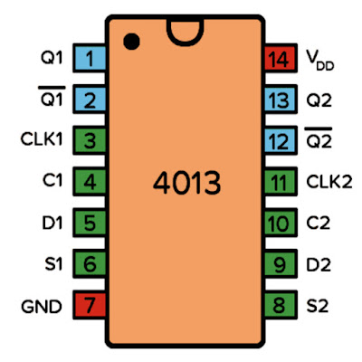
But ultimately I wanted to use the CD4013 IC, which is listed as a Dual D-Type Flip-Flop (the D being for Data). In the datasheet we see the following "function table":
And the pinout for the chip is as follows:
The video shows this working well as per the datasheet, and it was interesting that the output does not change when enable is HIGH, but only when enable has a rising edge.
I think next I'll try the JK Flip Flop to avoid the "ambiguous" case which seems to be the downfall of this circuit.
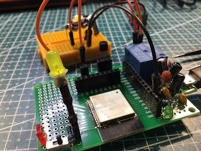
After recent arrivals in the ESP32 adapter and relay department I decided to put together a circuit that allows for remote switching of decent current (e.g. 10A).
The circuit is similar to the one shown below (with the ESP32 playing the part of the switch):
The high signal drives the mosfet (a BS170) which opens the relay and releases all the ergs for the LED. Soldered up it looks quite good (don't look underneath), excepting that the 5V to 3.3V DC converter (SSP7603) looks a little ugly with all the capacitors stuck onto it like barnacles!
More or less standard OTA code makes this easy to program over the air, and I was pretty chuffed to be able to change the frequency of two separate GPIO pins without actually wiring up the ESP32 to a computer.
Probably the only interesting thing about the code above is the use of millis() to fake multitask - I love that technique and it works really well on these devices.
On a smaller device (e.g. ATTiny13) I'd probably use interrupts and count the ticks to activate the GPIOs when a coded amount is reached. The ESP32 has a LOT of flash overhead though, so I took the lazy way this time!
I'm hoping I can continue to refine this idea and maybe use these guys around the place for remote sensing and control. Watch this space!
PMS150C, ULN2003 and the 28BYJ-48 Stepper Motor (Tiny Dancer)
I have had it in mind to start to know the Padauk microcontrollers a little better, and in particular the PFS154 and the PMS150C. It has been such a journey so far, with the concentration of effort mostly into the making of the open source programmer.
In the "still to do" basket are:
Do more than just blink LEDS
Mimic/translate ATTiny/Arduino code to Padauk
Learn more C-Code to better fit into the specs of the little fellas (the Arduino Uno/Nano is very generous and forgiving, and has multiple libraries - many bloated but functional)
Move from C-Code to Padauk assembly for speed, clarity and size.
The prospect of making the feature challenged (but cheap!) one-time programmable PMS150C drive a stepper motor reminds me very much of humans driving big machinery - such as here in Australia where tiny figures are dwarfed by Haul Pack trucks.
My plan was to make some stepper code work with Arduino (and appropriate libraries), then transfer the code to the very familiar ATTiny13, and finally the PFS154 (because it's multi-programmable, so testing is less stressful). The ultimate goal of the exercise is to use the one time programmable PMS150C.
In the end I only threw away two fried PMS150C chips, so I'm pretty happy about that!
It seems that a common way to control this guy is to use a ULN2003 Darlington Array chip, but somewhat unusually this is wrapped up in a module which allows 5V/12V versions and has blinking lights because, well, who doesn't love blinking lights?? <sigh>
I do have some ULN2003 chips about the place (somewhere...?), but the focus for this project is programming, so I'll use the OMG AMAZING™ light show version.
Getting an Arduino Uno to light em up and move the stepper was not problem - you simply install this library and then borrow the code from the examples given.
The stepper motor datasheet recommends the following sequence to turn the shaft:
Therefore instead of using the stepper library for the ATTiny13 version, I made an array of appropriate data and then stepped through it either backwards or forwards for "random" dancing.
Problems emerged when I "translated" this to the PFS154 and then to the PMS150C. I think the majority of the issues were wrapped up in the variable data types. I eventually simplified most of these to 0-255 by using the uint8_t data type.
The data types "int", "char", "byte" and even "uint16_t" were all too problematic for the PMS150C (although the PFS154 code was pretty much the same as the ATTiny13 code).
The change of data types also meant that I had to "tweak" the code, in particular the "random" number generator, quite a bit!
The resultant randomness is pretty awful, but that's a problem for another time (perhaps when I learn how to use the chip's comparator as an ADC).
#include <pdk/device.h>#include <delay.h>#include <stdint.h>#include "auto_sysclock.h"#include <stdlib.h>#include <stdbool.h> // important for booleanschar thesteps[] = {
// PMS150C pinout//// _________// / |// 1--|VCC GND|--8// 2--|PA7 PA0|--7// 3--|PA6 PA4|--6// 4--|PA5 PA3|--5// |__________| // IN 4, IN3, IN 2, IN 1// PA6, PA7, PA0, PA4// pins 3, 2, 7, 60b11000001,
0b11000000,
0b11010000,
0b01010000,
0b01010001,
0b00010001,
0b10010001,
0b10000001
};
uint8_t numberofsteps =0;
// change these as you please, my focus in this// project was not the "purity" of randomnessuint8_t myrand =201;
uint8_t xorpoly1 =0b10001011;
uint8_t xorpoly2 =0b10111010;
uint8_t throwspanner =61;
uint8_t spannercount =0;
uint8_tgimmerand(uint8_t small, uint8_t large) {
bool carry =false;
if (spannercount > throwspanner) {
myrand = myrand ^ xorpoly2;
myrand--;
spannercount =0;
}
if (((myrand) >>7) &1) {
carry =true;
}
myrand = myrand <<1;
if (carry) {
myrand = myrand ^ xorpoly1;
}
return (myrand/((255)/(large-small))+small);
}
boolisEven(uint8_t n) // faster than n%2==0?
{
return (!(n &1));
}
voidmain() {
PAC =0b11111001; // output pinswhile (1) {
// change these for "speed" of dancing
numberofsteps = gimmerand(4, 40);
_delay_ms(10);
if (isEven(numberofsteps)) {
for (uint8_t rotate =0; rotate < numberofsteps; rotate++) {
for (uint8_t clocker =0; clocker <8; clocker++) {
PA = thesteps[clocker];
PA = PA |0b00100000; // turns on LED
_delay_ms(1);
}
}
}
else {
for (uint8_t rotate =0; rotate < numberofsteps; rotate++) {
for (uint8_t clocker =7; clocker >0; clocker--) {
PA = thesteps[clocker];
PA = PA |0b00001000; // turns on LED
_delay_ms(1);
}
}
}
}
}
Amazingly the PMS150C (and the PFS154) do have an extra two "proper" GPIOs to play with after this program is installed (the ATTiny13's RESET pin can be used as a "weak" GPIO if needed), so you'll see blinking LEDS to indicate clockwise and counterclockwise dancing.
Lately I have been seeing a lot (A LOT!) of videos about "proper" connections. It's amazing that for years you might only rarely hear of a particular technical word like FERRULE, and then suddenly you can't watch a day of YouTube without it cropping up all over the place!
The one that spurred me into action was a lovely video (as always) from Great Scott, and indeed I have suffered some problems associated with dodgy soldered joints. Thus I put in an order and waited.
After the usual Pandelay I received a bunch of ferrules and a crimper, and so I am starting to replace some earlier compromised connections with these little fellas to increase the life and the stability of the devices on which they rely.