Saturday, March 27, 2021

0000 0000 0101 1010

Why PFS154? Part one...

Those who have been here for the (long and torturous) journey with Padauk chips have seen the following milestones (millstones?) much like episodes like in the sitcom "Friends":

        a) The one where I fry many PCBs (fail)
        b) The one where I use my one working programmer to...er...blink an LED (semi-success)
        c) The one where I make an unworkable "old man" version of the programmer (fail)
        d) The one where I "baked" working programmers in a cheap oven (for the win)
        e) The one where I blink a bright LED via a transistor

And if you have seen all of that and are shaking your head about the stupidity and waste, you may be asking yourself the obvious question - but why?

I have of course learned a great deal along the way and there is no doubt (in my mind at least) that this project has given more than it has taken, but a cloud still remains over the whole endeavour when on the shelf I have so many idle Padauk chips - what is the actual end game?

Well, for one, despite their low cost the major goal all along has been getting access to the lovely specs of these chips on the assumption they are not full of tiny socks (long story).

In particular the PFS154, which looks similar to my AVR buddy the ATTiny13, is interesting in that by comparison it is a bit of a muscly fellow, at around 20% of the cost. There's no ADC (grrr), a "feature" we will explore at a later time, but otherwise as Paul Keating might say "That's a beautiful set of numbers!".


First impressions are that the many PWM channels might be of some use in the long-running candle project. More channels surely means a better simulation of the real deal?

The ATTiny13 has two PWM channels (8 bit) and so all previous work on this project has been limited to these specs. I have in the past configured three-in-one SMD 5050 LED such that two of the three LEDs are attached to a "slow rise/fall" channel and one LED for a "fast rise/fall" channel using a three-in-one SMD 5050 LED.

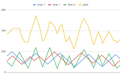
The result is a pretty good random flickering effect (peak intensity shown below in yellow). The plot is from 1000 points based on the code and then outputted to Serial on an Arduino Nano. The data was copied to a spreadsheet to make a pretty picture.


For three channels the result is quite different, with what I think is more natural "smoother" variation.


Some work still to be done:

1. Non-linear ramping (low pass filter or software?)

2. Separate ramping gradient for medium and fast ramping (e.g. different AND variably adjusted rates per ramp)

3. "Guttering" code - a natural phenomena whereby a candle will almost go out and then relight, for instance in response to a breeze.

4. Porting code in part or in entirety to assembly for efficiency.

5. Running the PFS154 at the lowest clock speed

6. Sleeping PFS154 between PWM adjustments?

The code itself was ported pretty much intact from an early ATTiny13-based version. I later developed that version into more efficient (smaller, faster) assembly code and as well wound the clock speed of the microcontroller down to around 128kHz. Is any of this possible also on the PFS-154? Watch this space.


Saturday, March 20, 2021

0000 0000 0101 1001

Attiny Bootloaders

Bootloaders are mysterious beasts - I have "bricked" many chips through clumsy setting and flashing of fuses on various micro-controllers. For instance, if you set the clock to an external 8Mhz crystal and then burn the bootloader, you will need an external 8Mhz crystal to either change the clock or to upload code. Makes sense in hindsight, right?

This "oversight" became such a regular occurrence that I ordered, and have used quite a few times, a high voltage fuse fixer (HVPP/HSVP programmer) which has brought back to life many an abused µC.

You can build your own HVPP if you wish, by just following these excellent instructions.

A large part of the confusion on my behalf arose early in my AVR dabbling when I bought a device marketed as a "programmer"

I had also at that time bought some dirt cheap DIP8 ATTiny13 chips so I was super keen to make a ... blinking led circuit? Loading up the famous blinky sketch on the Arduino IDE I plugged in the ATTiny13 into the cradle and then nudged the USB cable into a port on my computer and...

Due to not understanding the whole correct orientation of the chip thing, the ATTiny13 was literally smoking, the "programmer" was fried, and then the computer involuntarily shutdown.* Not the most auspicious start to my AVR programming life.

Very soon after this scarring experience I discovered the Arduino ISP sketch, found out how to hook up an Arduino to an ATTiny for burning fuses and programming, and forgot about the whole "cheap so-called programmer smoking up the room" episode.

Until recently that is! In order to conjure up topics for this blog and channel I literally grab a random component - and so I was fishing about for inspiration and pulled out one of these tiny DIP8 programmers from the buckets. Oh no! There were flashbacks including of course the well known smell of burning components (which was prophetic).

Nonetheless - given it is a few years on and perhaps I could be a bit wiser (?!), I plugged in an ATTiny85 (the correct way), and loaded up some blinky goodness, then pushed "compile and upload" only to be greeted with amused silence from the Arduino IDE and some distinctly non-blinking of LEDs.

So here I am again (with the benefit of hindsight and experience?) seeing if I can usefully employ these devices. Crucial to the process is the idea that this little board does not have any USB interface and so we need to use a "virtual USB" protocol encapsulated in a bootloader. Which came first, the chicken or the bootloader?

Most of the work in this area has been done by the "MicroNucleus" team. The plan for this little board is thus to:

1. Load the Micronucleus bootloader to a "vanilla" ATTiny85 using USB-ISP
2. Program the ATTiny85 directly from the board using the Micronucleus bootloaders V-USB protocol
3. Try to upgrade/load the bootloader and program using the board only
4. Try to extend the bootloader from ATTiny85 to ATTiny13

See below for the video of these steps and their various successes.


*postscript: I blew up another one in the exact same manner making this post/video <sigh>


Saturday, March 13, 2021

0000 0000 0101 1000

Rowing Clock

I've been giving the rowing machine a bit of a hammering over the last year or so. The plan is to shed my perpetual winter plumage (aka fat) and trim down to a point where I don't have to continually invest in a whole new wardrobe.

The problem (as a numbers guy) has been the ... er ... numbers on the machine. It's a comprehensive readout that comes with the machine and it successfully distracts me away from the business of proper form and zen-like concentration on the actual rowing. I'm always chasing the numbers.

After a couple of visits to the physiotherapist to confirm that I am old and fat and shouldn't be chasing numbers I switched off the readout and used instead my phone countdown to measure the time rowed. It worked semi-well until my weird brain started to panic and as I was sweating away I became distracted through wondering if the damn phone was set correctly, and whether or not I was going to be rowing until Christmas.

So what I needed was a visual way of seeing the rowing but without the actual numbers. Inspired by a pileofstuff video I planned out a little 3D printed box full of goodies including an LED Ring, a 4-digit 7-segment display (TM1637), rotary encoder and buzzer as follows.

I also used a spreadsheet to draw the pattern I had imagined, just to make the coding part of the project a little easier to construct.
The code was in several sections:
  1. Set time to row
  2. Countdown to rowing start
  3. Countdown to rowing finish
  4. Warmdown
  5. Shutdown
#include <OneButton.h>
#include <Rotary.h>
#include <TM1637Display.h>
#include <FastLED.h>
#include "LowPower.h"

#define NUM_LEDS 16
#define DATA_PIN 7
#define CLK 11
#define DIO 10
#define buzzer 9

uint32_t intervaldelay = 0;

CRGB leds[NUM_LEDS];

volatile byte rowingmins = 1;
byte minmins = 1;
byte maxmins = 180;
volatile byte cw = 0;
volatile byte clicked = 0;
byte buzzdelay = 200;

TM1637Display display(CLK, DIO);
Rotary r = Rotary(3, 2);
OneButton button(4, true);

void setup() {

  FastLED.addLeds<WS2812, DATA_PIN, GRB>(leds, NUM_LEDS);
  FastLED.setBrightness(20);
  PCICR |= (1 << PCIE2);
  PCMSK2 |= (1 << PCINT18) | (1 << PCINT19);
  sei();
  pinMode(buzzer, OUTPUT);
  button.attachClick(singleclick);
  display.setBrightness(4);
  setupcolour(0, 0, 0, 0);
}

void setupcolour(byte numgreen, byte numyellow, byte numred, byte numoff) {
  byte whichlight = 0;
  byte endlight = numgreen;
  for (byte countgreen = 0; countgreen < endlight; countgreen++) {
    leds[countgreen] = 0x00CC00;
    whichlight++;
  }
  endlight = whichlight + numyellow;
  for (byte countyellow = whichlight; countyellow < endlight; countyellow++) {
    leds[countyellow] = 0xFF9900;
    whichlight++;
  }
  endlight = whichlight + numred;
  for (byte countred = whichlight; countred < endlight; countred++) {
    leds[countred] = 0xCC0000;
    whichlight++;
  }
  endlight = whichlight + numoff;
  for (byte countblack = whichlight; countblack < endlight; countblack++) {
    leds[countblack] = 0x000000;
    whichlight++;
  }
  FastLED.show();
}

void precount() {

  for (byte showcount = 0; showcount <= 16; showcount++)  {
    setupcolour(showcount, 0, 0, 16 - showcount);
    delay(80);
  }

  setupcolour(0, 0, 0, 16);
  delay(500);

  setupcolour(16, 0, 0, 0);
  tone(buzzer, 2000);
  delay(buzzdelay);
  noTone(buzzer);
  delay(8000);

  setupcolour(12, 0, 0, 4);
  tone(buzzer, 2000);
  delay(buzzdelay);
  noTone(buzzer);
  delay(8000);

  setupcolour(8, 0, 0, 8);
  tone(buzzer, 2000);
  delay(buzzdelay);
  noTone(buzzer);
  delay(8000);

  setupcolour(4, 0, 0, 12);
  tone(buzzer, 2000);
  delay(buzzdelay);
  noTone(buzzer);
  delay(1000);

  setupcolour(3, 0, 0, 13);
  tone(buzzer, 2000);
  delay(buzzdelay);
  noTone(buzzer);
  delay(1000);

  setupcolour(2, 0, 0, 14);
  tone(buzzer, 2000);
  delay(buzzdelay);
  noTone(buzzer);
  delay(1000);

  setupcolour(1, 0, 0, 15);
  tone(buzzer, 2000);
  delay(buzzdelay);
  noTone(buzzer);
  delay(1000);

  tone(buzzer, 2000);
  delay(buzzdelay);
  noTone(buzzer);

}

void warmdown() {

  for (byte downcount = 1; downcount < 4; downcount++) {
    setupcolour(0, 0, 16, 0);
    tone(buzzer, 2000);
    delay(buzzdelay);
    noTone(buzzer);
    delay(250);
    setupcolour(0, 0, 0, 16);
    delay(250);
  }

  for (byte warmcount = 16; warmcount >= 0; warmcount -= 1) {
    setupcolour(0, warmcount, 0, 16 - warmcount);
    delay(4000);
  }
}

ISR(PCINT2_vect) {
  unsigned char result = r.process();
  if ((result == DIR_CW) && (rowingmins < 180)) {
    rowingmins++;
  }
  else if ((result == DIR_CCW) && (rowingmins > 1)) {
    rowingmins--;
  }
}

void singleclick() {
  clicked = true;
}

void settime() {

  while (!clicked) {
    button.tick();
    display.showNumberDec(rowingmins);
  }
  PCICR = 0; //disable pin change interrupts

}

void loop() {

  settime();
  precount();
  display.clear();
  intervaldelay = rowingmins * 60000 / 32;

  for (byte countdown = 16; countdown > 0; countdown--) {
    setupcolour(countdown - 1, 1, 0, 16 - countdown);
    delay(intervaldelay);
    setupcolour(countdown - 1, 0, 1, 16 - countdown);
    delay(intervaldelay);
  }
  warmdown();
  LowPower.powerDown(SLEEP_FOREVER, ADC_OFF, BOD_OFF);

}


Next I needed to prototype the setup on a breadboard to make sure that all the components (and code) were working as expected.

Finally I soldered up the whole shebang and shoehorned the lot into the 3D enclosure. The only addition in the end was a little ice-blue LED on the side to indicate that the box is "live" just in case I forget to turn in off as I have my post-workout heart attack.

It works exactly as needed and it was nice to build such a useful project with so many different aspects coming together to make the final result.


Saturday, March 6, 2021

0000 0000 0101 0111

CD4073 three input AND gate

I watch a bit of YouTube (shock) including the "Missionary Bush Pilot". Ryan the pilot is meticulous with his preparation and flying, and the scenery of course is dazzling, but most of all I am in awe of his ability to keep up a high quality narration as he goes about his piloting. My videos by comparison are replete with "ums" and "ahs" and all I'm doing is soldering a few LEDs together!

One really cool part of Ryan's preparation is the use of a rocker switch array which is his checklist.

It's a good design, but seems to lack the required number of LEDs to be truly epic. So recently I pulled out a CD4073 three-input AND gate from the buckets and decided to use it to emulate a checklist style panel.

I don't fly a plane, but I do ride a motorcycle - so this one could be about boots, helmet, gloves, tyre pressure, battery charge, headlight and maybe attitude!

If all the switches are "green" to go, then an eighth switch could be activated to actually start the bike/plane.

Firstly, I needed to check how multiple AND gates might work together, so I used iCircuit to test a possible configuration involving only two input AND gates.  Then I added a transistor NOT gate and a transistor switch indicate red or green for go.

Switches open, red light
Switches closed, green light

On the breadboard it works fine - should I strap it to the cowling/screen?