The LED bench lights and controller I built awhile back has been going well, excepting a bit of inrush current when I turn on the AC/DC converter.
Great Scott did a video and great explanation for a circuit to address this problem, using a Solid State Relay (SSR) and a few simple components to throttle the inrush from an inverter.
The issue for me and using his circuit is that I don't want to make a soft starter for an AC device (inverter), but rather a DC device (LED lights).
The SSR and Great Scott's circuit will work (despite the online naysayers), but will just latch the LEDs once when it has soft started the circuit, which is in truth all I need it to do. When it is not being used it is turned off - I don't turn it on and off during use.
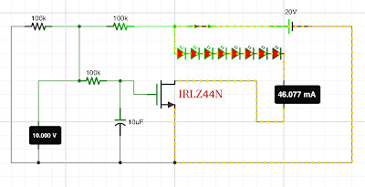
Despite that, and because I'm a bit quirky at times, I wanted to try another avenue and so I designed via the simulator an analogous DC appropriate circuit built around the IRLZ44N N-channel Mosfet.
A Mosfet is voltage activated, not current activated like a BJT, and so I used a couple of 100k resistors in a voltage divider configuration to reduce the 20V coming in from the AC/DC converted to just 10V. According to the data sheet, the IRLZ44N should then be wide open!
The 10V is then channelled via an RC circuit to the gate of the mosfet. The RC combo gives the time it takes for the mosfet to fully open according to these calculations.
After a quick prototype and some testing of this simple little circuit in situ I soldered it all up on a PCB and shoved it into the LED supply box - and it works!
I probably should have spent some time looking into the horrible hot glue mess for the display, but...quirky!
For some reason (old age?) I find the idea of programming a device via WiFi quite astonishing. That such a thing exists, that I can do it, and that it works for me in the end seems miraculous!
In the video below I grab an ESP-12S, solder it to a PCB adaptery thingo and program it up with the following OTA code...
For some reason (late night purchasing?) I received a combo Nano and Wireless module in the mail and thought it was a pretty cool WiFi capable Nano.
But after investigation I found it was actually an NRF24L01 module sandwiched into the Nano form factor (an RF-Nano, not to be confused with Nano-RF!).
Then began what I thought was going to be a simple project to link two of these together and test the communication distance. It was not a simple project!
To go through all the problems in detail would take too long, but here's a quick dot point summary:
The microcontroller at the heart of the RF-Nano purportedly is a clone of the ATMega328p known as the LGT8F328P. It comes with some impressive stats - including 32MHz clock speed. But...all attempts to use known board core combos to communicate with the chip failed. Eventually I caved in and used the standard Nano board core - the ATMega328p version, and it worked?!
The LGT8F328P microcontroller supposedly can run at 32MHz - after a few experiments documented in the video below my little darling could barely tick along at 4MHz?!
4MHz means that things like NRF24L01 communication and ADC stuff seem compromised - great! Now I need to burn the bootloader and hope overclocking is not an issue?
There are various incarnations of this FrankeNano, which means that the critical CE and CSN pins involved in communication between the Nano and the NRF24L01 module may well be different to the library - advice: follow your traces carefully.
There is no documentation for the use of an external antenna, so I just flipped the zero ohm resistor/jumper myself - although I found that this configuration did not improve performance at all, and in fact may have degraded the communication distance between modules. I'm currently experimenting with different external antenna combos.
The ICSP headers on the RF-Nano have been sacrificed for the NRF24L01, so when I'm ready to blow up one of these I'll use the pins on the Nano itself and try to clock that microcontroller back up to useable speeds.
You will need a decent power supply, nice chunky current and some beefy capacitors to help with communication - there is still much to be discovered about this strange beast. Good on the Emakefun crew for giving it a shake - it's a worthy idea that I think might need a bit of solid documentation and some well commented example code to make it fly.
Speaking of code - I modified the following that I found on this site, and the send/receive combo looks like this...
There are a few IoT projects floating about and an important part of the circuits utilising ESP8266s or ESP32s are good quality voltage regulators which can deliver a decent current at 3.3V without too much drop out and with a low quiescent current.
I've used HT7333s before and they've been OK, but there appeared on my radar the SSP7603 series of LDO voltage regulators which looked pretty trick with some great overall specs.
They came in a SOT89 package and were pretty cheap! The first thing was to find a suitable adapter and solder them up according to the datasheet. I used 10µF/100nF combo instead of the 1µF tantalum suggested, but otherwise it was as follows.
Just for piece of mind I then tested the little guy under different input voltages and loads - it performed perfectly, even current limiting when appropriate.
It's my new favourite - quite a powerhouse for the size and price!
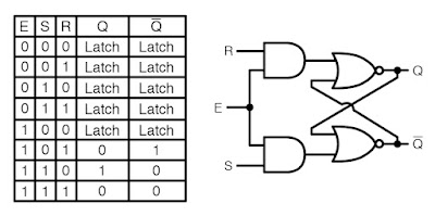
The problem with an SR Latch is the so-called "illegal state" whereby the circuit cannot consolidate the signals into a cohesive output and some weird random oscillations take place.
In order to straighten that out, there is a "gated" SR Latch that employs a couple of AND gates to "pre-load" the input signals for the NOR gates so that they don't wig out.
Further, the E (enable) input can be swapped out for a clock, and one of the inputs can be inverted, to create the very useful D Flip Flop, which not only has it's applications in computer logic, but also makes a nice circuit to, for instance, check and debounce switch inputs.
While mucking around with the simulator trying to figure out how this circuit works I decided to explore replacing the AND gates with NOR gates.