It seems like the annual December project is to muck around with some festive LEDs, and what better way to finally introduce the famous 3 cent PMS150C than upgrading the previous ATTiny13 lights to the frightfully shy Padauk alternative.
Elements of this insanity over the last two years have been:
1. Scouring the forum for the latest information in the process of reverse engineering the chips and the programmer.
2. Making several versions of the programmer, until finally one works
3. Learning about how to program the PFS154 (MTP) so that I can try the PMS150 (OTP)
4. Use my usual insane Trial and Error and Error and Error Method™️ of programming until the resultant code works.
...and by playing with the DIV## numbers I was able to get a flashing sequence pretty much on par with the old ATTiny13 version. A future video might involve hooking up my pathetic DSO138 oscilloscope to investigate that timing a little more closely.
Another "evolution" this year has been the LED size, down from 1206 to 0805. I'm not sure why, but I am assuming the smaller ones use less current? They certainly still light up a dark room though!
Finally it transpires that the GPIO maximum current in the PMS150C is puny at around 5mA - so I ditched the current limiting resistor and placed the LEDs in a charlieplexing arrangement from Pin5 to Pin6.
Works a treat as you can see below, and in tests it has shown more longevity in flashing away long after last year's version has expired. Good one! Has the ATTiny13 been de-throned as Champion of both austerity and efficiency?
When it arrived, the ESP-01S was a mighty upgrade from the ESP-01, chiefly doubling the flash memory from 512KB to 1MB. Also, a nice onboard LED!
There are 8-pin 4MB flash chips available which continue to be a cheap source of extra programming space for some projects.
For instance, on this blog (and YT video), I've taken a look at how these budget chips can be used as extra storage for the Arduino Uno.
For around AU25 cents each the 25Q32FVSIG 4MB ICs can be swapped in for the 1MB ESP-01S versions and, if the solder gods are with us, increase the program space available.
Note that I believe that the ESP8266 can only address a maximum of 4MB so my ideas of creating an IoT super-race may have (for now) been dashed.
In the meantime, from this website comes some code I "borrowed" to set up a webserver with a slider. When "slid", the server controls the PWM output of a GPIO on the device.
Recently on a video I was raging about how useless the internet was becoming with all the adverts. One comment underneath spurred/shamed me into action:
As it turns out my Raspberry Pi box of SBCs was emptier than I remembered, however my Orange Pi box was replete with possibly suitable SBCs, including an Orange Pi PC left over from a previous blog and video.
I liked the auto-cooling version I had previously made, and now seemed like a good time to press it into service cutting out all of those pesky online adverts!
The Pi-Hole advert blocking project has a bit of history now, and the community behind it is mature and productive. Due to my nerdiness I went to their github site and followed installation and tips etc. The software installed fine over the top of armbian for the Orange Pi PC.
There were a few weird hiccups along the way (aren't there always?):
1. The startup script for the fan (see this link) did not work, due to (new?) requirements that startup scripts have START|STOP|RESTART|ETC blah blah which I don't quite understand at this point. Fortunately I had a working image which include the fantemp.sh script, so I used that as a base for this project.
2. I wanted to use the Orange Pi Zero 2 which would be perfect for the role - and I have one in my Orange Pi box, but software support for the H616 processor is not great at the time of making this project - if it improves then I will have a look at possibly swapping out to this SBC.
3. Router issues - my ISP issued router™ is an idiotic piece of junk. The ISP will not support a customer with any other piece of hardware (!!), so I have stuck with it for a few years - but this Christmas I have asked Santa to bring me a better router. Until then, to get to the part of the router that allows me to specify the Orange Pi(hole) as the DNS server, I need two 64 bit passwords embedded (but not hidden) in their source code <heavy sigh>. So right click, download
4. GPIO access - to control the fan I needed access to a GPIO which then triggers an SS8050 transistor to draw enough current for the fan. Unfortunately that took a bit of a while to sort out, and in the end I used this github site to solve the problem.
5. WiFi or cable? In the end I connected the Orange Pi PC directly to the router via an ethernet cable AND I was able to power it from the router through a USB port - a neat option now sitting side-by-side with the router.
Part of the program to monitor and automate some things around the property naturally enough includes extending the WiFi network to cover a wider area. There are a number of ways of doing this, including:
1. Buying a decent router and channelling heaps of power into it for coverage
3. Coming up with some half-baked plan to use $1 ESP-01 devices running on solar power (in Tasmania!)
Of these options, which do you think this post is essentially about?
There are a number of options for setting up such a (cheap) extended network, and it may take a few blogs/videos to explore and evaluate some options. On my list is the following:
1. Can I program the ESP-01 to accept home WiFi? 2. Which extender/repeater software for the ESP-01 suits my needs? 3. Test the network under various conditions to help me make the decision 4. Work on Solar/Battery combinations that work for spreading the network around a rural property
5. Design and 3D print a weather-resistant project box
On the programming front, the little adapters are great, however there seem to be two main types. One is just a cradle for the ESP-01 and needs some soldering and a button added to be used as a programmer (see video), whilst the other comes with an integrated button and can be switched between "PROG" and "UART" mode.
Then it's a matter of choosing your programming method - you can use Esptool, Espressif's tools or (as in my case) the Arduino IDE.
Once the connections and programming was sorted (i.e. can I blink a LED!) I then used the following OTA code modified from the ESP8266 WiFi extender code:
// NAPT example released to public domain#if LWIP_FEATURES && !LWIP_IPV6#define HAVE_NETDUMP 0#ifndef STASSID#define STASSID "*****************"#define STAPSK "*****************"#endif#include <ESP8266WiFi.h>#include <ESP8266mDNS.h>#include <WiFiUdp.h>#include <ArduinoOTA.h>#include <lwip/napt.h>#include <lwip/dns.h>#include <LwipDhcpServer.h>constchar* ssid = STASSID;
constchar* password = STAPSK;
constchar* host ="HostName";
#define NAPT 1000#define NAPT_PORT 10voidsetup() {
Serial.begin(115200);
Serial.printf("\n\nNAPT Range extender\n");
Serial.printf("Heap on start: %d\n", ESP.getFreeHeap());
#if HAVE_NETDUMP#include <NetDump.h>void dump(int netif_idx, constchar* data, size_t len, int out, int success) {
(void)success;
Serial.print(out ? F("out ") : F(" in "));
Serial.printf("%d ", netif_idx);
// optional filter example: if (netDump_is_ARP(data))
{
netDump(Serial, data, len);
//netDumpHex(Serial, data, len);
}
}
#endif#if HAVE_NETDUMP
phy_capture = dump;
#endif// first, connect to STA so we can get a proper local DNS server
WiFi.mode(WIFI_STA);
WiFi.begin(ssid, password);
while (WiFi.status() != WL_CONNECTED) {
Serial.print('.');
delay(500);
}
Serial.printf("\nSTA: %s (dns: %s / %s)\n",
WiFi.localIP().toString().c_str(),
WiFi.dnsIP(0).toString().c_str(),
WiFi.dnsIP(1).toString().c_str());
// give DNS servers to AP side
dhcpSoftAP.dhcps_set_dns(0, WiFi.dnsIP(0));
dhcpSoftAP.dhcps_set_dns(1, WiFi.dnsIP(1));
WiFi.softAPConfig( // enable AP, with android-compatible google domain
IPAddress(172, 217, 28, 254),
IPAddress(172, 217, 28, 254),
IPAddress(255, 255, 255, 0));
WiFi.softAP("WiFi-Mesh", STAPSK);
Serial.printf("AP: %s\n", WiFi.softAPIP().toString().c_str());
Serial.printf("Heap before: %d\n", ESP.getFreeHeap());
err_t ret = ip_napt_init(NAPT, NAPT_PORT);
Serial.printf("ip_napt_init(%d,%d): ret=%d (OK=%d)\n", NAPT, NAPT_PORT, (int)ret, (int)ERR_OK);
if (ret == ERR_OK) {
ret = ip_napt_enable_no(SOFTAP_IF, 1);
Serial.printf("ip_napt_enable_no(SOFTAP_IF): ret=%d (OK=%d)\n", (int)ret, (int)ERR_OK);
if (ret == ERR_OK) {
Serial.printf("WiFi Network '%s' with same password is now NATed behind '%s'\n", "Charis-Mesh", STASSID);
}
}
Serial.printf("Heap after napt init: %d\n", ESP.getFreeHeap());
if (ret != ERR_OK) {
Serial.printf("NAPT initialization failed\n");
}
ArduinoOTA.setHostname(host);
ArduinoOTA.setPassword("MyPass");
ArduinoOTA.onError([](ota_error_t error) {
(void)error;
ESP.restart();
});
/* setup the OTA server */
ArduinoOTA.begin();
Serial.println("Ready");
}
#elsevoidsetup() {
Serial.begin(115200);
Serial.printf("\n\nNAPT not supported in this configuration\n");
}
#endifvoidloop() {
ArduinoOTA.handle();
}
The video below shows this system in a link of WiFi SSIDs stretching about 60m down the driveway as per this diagram:
I'm currently evaluating a slightly different way of putting the network "Mesh" together, but I'll save that for another video/blog.
The next part of this crazy project is to scale up the 8-bit random numbers to 16-bit. An LFSR basically works by a LSL/EOR combo, and the 16-bit version is no different.
; AVR ASM program to make "random" 16-bit numbers
; using LFSR with a seed, and two spanners!
; A N Peck Sat 21 Aug 2021 11:02:58 AEST
.nolist
.include "tn13Adef.inc" ; Define device ATtiny13A
.list
.equ span1= 23 ; count before spanner1 thrown
.equ spanum1= 7 ; size of spanner1
.def spanner1= r18 ; spanner1 counting register
.equ span2= 37 ; count before spanner2 thrown
.equ spanum2= 3 ; size of spanner2
.def spanner2= r19 ; spanner2 counting register
.equ seed= 2901 ; starting seed - happy birthday
.equ poly1= 13 ; change these
.equ poly2= 24 ; polynomials if need
.dseg
.org SRAM_START
.cseg
.org 000000
rjmp Main ; Reset vector
Main:
; initialise stack
ldi r16, Low(RAMEND)
out SPL, r16
; seed for LFSR loaded
ldi r16, low(seed)
mov r7, r16
ldi r16, high(seed)
mov r6, r16
; polynomial loaded
ldi r24, poly1
ldi r25, poly2
; spanners loaded
ldi r18, span1
ldi r19, span2
Loop:
; generate random number
rcall rand_16
checkspanner1:
subi spanner1, 1 ; decrement spanner1 count
brne nospanner ; branch if not at zero
mov r16, r7 ; throw spanner1 (subtraction)
subi r16, spanum1
breq nozero1 ; result must be nonzero
mov r7, r16
nozero1:
ldi spanner1, span1 ; reset spanner1 count
checkspanner2:
subi spanner2, 1 ; decrement spanner2 count
brne nospanner ; branch if not at zero
mov r16, r6 ; throw spanner2 (addition)
subi r16, -spanum2
breq nozero2 ; result must be nonzero
mov r6, r16
nozero2:
ldi spanner2, span2 ; reset spanner2 count
nospanner:
; save registers to file with modified nop
nop
rjmp loop
rand_16:
lsl r6 ; shift first
rol r7 ; roll
brcc noxor ; check flag
eor r6, r24 ; XOR if needed
eor r7, r25
noxor:
ret
To test the randomness of the generated numbers I used a special version of Gerd's AVR Simulator (thanks Gerd!) which allowed me to capture the register values in a csv file. I then used CONCATENATE and HEX2DEC in a spreadsheet to make a long list of decimal values in the range 0 to 65535 (around 6000 values).
Finally I imported this data as raw input into Audacity and then listened to the noise resulting.
This allowed me to tinker with the code until a "white noise" signal resulted - I especially worked two "spanners" into the code whereby after a certain pre-determined number of numbers the random number was "jumped" up or down by a specific amount. Crude, but effective.
Another option would be to swap nibbles at "random" points (I may still code this).
The next part of this project is to see how easy it is to incorporate assembly code such as this (based on the ATTiny13 AVR instruction set) to the PFS154. Watch this space.
For such a long time I resisted the lure of the logic chip - why should I bother when a microcontroller can do all that and more for little more than spare change?
Well, now that microcontrollers (if you can buy them) cost millions of dollars each and logic chips are still relatively cheap - that side of the equation has changed!
But also I have to admit I've fallen a little in love with these "wire critters". One element of the change of heart has been reading Forrest Mims' excellent notebook series, many of which contain fascinating circuits based on single or combinations of different logic chips.
There are many useful circuits (non-microcontroller based) that can be constructed, such as the following button debouncing circuit made with the CD4001 (see last blog and video):
While playing around with some ideas for applications of "latching" circuits I decided that a long held issue of mine found in most school science laboratories may be addressed with a circuit involving this IC.
The problem has been that there is only one big red panic button in the average school laboratory used in an emergency to shutdown gas, electricity and/or water. I'd like to have one panic button at each "station" which can shut down the entire grid.
To accomplish this I built a simulated version and it seemed to work both for a single station, but also for multiple stations as you would find in an actual laboratory.
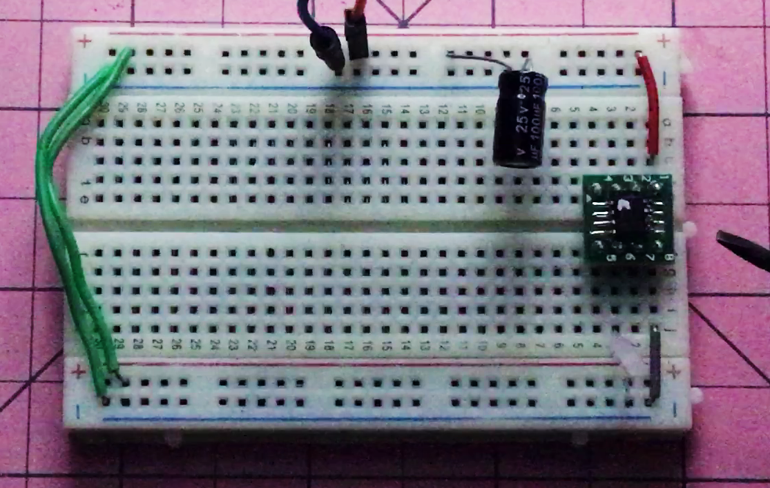
The simulation worked fine, so then I constructed the circuit on a breadboard and ran it through its paces.
The lab tech at work reckons that the idea is a winner, but is worried about students pushing the big red button just to annoy everyone. That is an entirely possible (probable) scenario, but can easily be addressed with the usual carrot/stick training that we employ for other "dangerous" or tricky laboratory items.
I've always been more of a coder learning electronics than an electronics peep learning coding, but I'm coming around to the notion of CMOS logic chips doing the work for simple circuits - particularly with the price of micro-controllers at the moment.
For around AU$0.06 each the CD4001 has a lot of handy uses. Using 0033mer as inspiration, I decided to make a classic relaxation oscillator feeding into a flasher suitable for car indicators.
It's an ingenious little circuit (as is usual with 0033mer) and it worked perfectly the first time. It does make me wonder if the indicators on cars use a similar system and, if not, will we return to logic driven circuits in cars as the micro-controller market continues convulsing?
I spent quite a few happy hours fiddling around with traffic light changers after my last blog and video which used the PFS154 and a button to make the changes. The crazy part is that there is not one single traffic light on my 35 minute commute to work - so...huh?
Anyway, first I looked at an interrupt driven change on the ATTiny13 version, then a simple loop driven change for an ESP32.
BTW, there are so many incarnations of the ESP32 that the list covers several pages on my Arduino-IDE.
After choosing the appropriate variant in the IDE I coded the following three versions:
1. Button press activated
2. WiFi activated
3. Bluetooth activated
Button Press:
int red = 13;
int yellow = 12;
int green = 14;
int button = 23;
int buttonValue = 0;
voidsetup(){
pinMode(button,INPUT);
pinMode(red,OUTPUT);
pinMode(yellow,OUTPUT);
pinMode(green,OUTPUT);
pinMode(button,INPUT);
digitalWrite(red,HIGH);
}
voidloop(){
buttonValue = digitalRead(button);
if (buttonValue == HIGH){
changeLights();
delay(4000);
digitalWrite(green, LOW);
digitalWrite(yellow, HIGH);
delay(1000);
digitalWrite(yellow, LOW);
digitalWrite(red, HIGH);
delay(2000);
buttonValue = LOW;
}
}
voidchangeLights(){
// red off, yellow for 1 seconds
digitalWrite(red, LOW);
digitalWrite(yellow, HIGH);
delay(1000);
// turn off yellow, then turn green on
digitalWrite(yellow, LOW);
digitalWrite(green, HIGH);
}
// the following are the RGB leds for the C3
constbyte red = 3;
constbyte green = 4;
constbyte blue = 5;
#define SERVICE_UUID "6E400001-B5A3-F393-E0A9-E50E24DCCA9E"#define CHARACTERISTIC_UUID_RX "6E400002-B5A3-F393-E0A9-E50E24DCCA9E"#define CHARACTERISTIC_UUID_TX "6E400003-B5A3-F393-E0A9-E50E24DCCA9E"voidchangeLights() {
digitalWrite(red, HIGH);
digitalWrite(green, HIGH);
digitalWrite(blue, LOW);
delay(2000);
digitalWrite(red, LOW);
digitalWrite(green, HIGH);
digitalWrite(blue, LOW);
delay(4000);
digitalWrite(red, HIGH);
digitalWrite(green, HIGH);
digitalWrite(blue, LOW);
delay(2000);
digitalWrite(red, HIGH);
digitalWrite(green, LOW);
digitalWrite(blue, LOW);
}
classMyServerCallbacks: public BLEServerCallbacks {
voidonConnect(BLEServer* pServer) {
deviceConnected = true;
};
voidonDisconnect(BLEServer* pServer) {
deviceConnected = false;
}
};
classMyCallbacks: public BLECharacteristicCallbacks {
voidonWrite(BLECharacteristic *pCharacteristic) {
std::string rxValue = pCharacteristic->getValue();
if (rxValue.length() > 0) {
for (int i = 0; i < rxValue.length(); i++) {
}
if (rxValue.find("G") != -1) {
changeLights();
}
}
}
};
voidsetup() {
pinMode(red, OUTPUT);
pinMode(green, OUTPUT);
pinMode(blue, OUTPUT);
digitalWrite(red, HIGH);
digitalWrite(green, LOW);
digitalWrite(blue, LOW);
BLEDevice::init("Traffic Light Changer");
BLEServer *pServer = BLEDevice::createServer(); pServer->setCallbacks(new MyServerCallbacks());
BLEService *pService = pServer->createService(SERVICE_UUID);
pCharacteristic = pService->createCharacteristic(
CHARACTERISTIC_UUID_TX,
BLECharacteristic::PROPERTY_NOTIFY
);
pCharacteristic->addDescriptor(new BLE2902());
BLECharacteristic *pCharacteristic = pService->createCharacteristic(
CHARACTERISTIC_UUID_RX,
BLECharacteristic::PROPERTY_WRITE
);
pCharacteristic->setCallbacks(new MyCallbacks());
pService->start();
pServer->getAdvertising()->start();
}
voidloop() {
if (deviceConnected) {
}
delay(1000);
}
Given the distinct dearth of traffic lights in Tasmania, I'm not sure how directly useful any of these devices will be in shortening my daily commute, but I can say that it opens up some possibilities for monitoring sensors and activating motors/pumps, etc, around the property. So perhaps overall it was a useful exercise!?
I also "enjoyed" the wrestle with the C3-BLE version of the ESP32, which I think may be very interesting to play with in the future.
The world is a wacky place at times - and right now it is difficult to get a relatively common IC like the STM32. Supply these days is often an issue, and price is certainly becoming an issue.
In September 2020 I bought 10 STM32F103R8T6 ICs to make the Pesky Padauk Programmer for the very reasonable cost of AUD $11.30 (for all 10) including delivery. In September 2021 I spied the following at my usual "cheap" supplier:
Yikes! So when a new PCB Padauk Programmer based on Tim's design turned up recently, I thought I'd desolder the STM32 chips from some of my previous numpty versions and try them in the new design.
Result? More or less successful! I think some of those previously used STM32s were fried from my amateur attempts to make this programmer. They have tiny fragile pins, and I have gross fine motor skills instead of the required fine gross motor skills!
At some point I will also want to, for the "intellectual stimulation", desolder a STM32F103R8T6 and/or STM32F103R6T6 from a "blue pill" to see if I can make that work, but that will have to be the subject of another video and blog I think!
Squeezing down the power of a PFS154 until it gasps
There are days when I wish that I had never heard of the magnificent reverse engineering project on EEVBlog for the Padauk range of microcontrollers. It is a wonderful piece of work put together by a talented group of individuals, but it is also a very deep rabbit hole from which it is difficult to escape.
There are other days when I claw back some sanity with a little win over this processor. It is often after trawling through datasheets, blogs and forums and piecing together a few snippets of code or advice that I have these tiny victories.
I've always got my eyes on the prize of having solar "candles" driven in part by these "cheap" devices. I write "cheap" even though the cost of time and components for the programmers is surely ridiculous (and I cheerfully avoid any damning tallies).
Here are some of the requirements that have contributed to this goal:
Feature
Blog
Video
Designing a circuit that collects solar energy and can deliver that power reliably to a microcontroller
One of the joys of the ATTiny13 based candle is the very low energy requirements. I was able to run the chip with minimal energy requirements by lowering the clock frequency (128Mhz) and the voltage (3V). Now we are at a similar point with the Padauk version.
So I was chuffed to see Tim on his blog talking up the low energy blinker he made from the PFS154 - complete with code!
/* --------------------------------------------------- Ultra Low Power LED flasher LED is connected to PA4 and is high active. Jan 16th, 2021, CPLDCPU - Initial version ---------------------------------------------------- */#include <stdint.h>#include <pdk/device.h>#include <pdk/delay.h>unsignedchar_sdcc_external_startup(void)
{
PDK_SET_FUSE(FUSE_IO_DRV_LOW); // Set output driving strength to low
CLKMD = CLKMD_ILRC | CLKMD_ENABLE_ILRC | CLKMD_ENABLE_IHRC;
CLKMD = CLKMD_ILRC | CLKMD_ENABLE_ILRC ;
// Note: it is important to turn off IHRC only after clock settings// have been updated. Otherwise the CPU stalls.return0; // perform normal initialization
}
voidmain(void)
{
// Toggling PA4 at ILRC (53kHz): 86 µA// Toggling PA4 at ILRC_dev16 (53kHz): 66.7 µA// Stopsys with 5V: 0.5 µA// The watchdog cannot wake up from stopexe!!
PADIER =0; // disable pins as wakeup source
PBDIER =0; // Also port B needs to be disabled even if it is not connected// to the outside of the package. touching the package can introduce // glitches and wake up the device
INTEN =0; // Make sure all interrupts are disabled
INTRQ =0;
MISC = MISC_FAST_WAKEUP_ENABLE; // Enable faster wakeup (45 clocks instead of 3000)// This is important to not waste energy, as 40µA bias is already added during wakeup time// Configure timer two for output on PA3// --> Works, timer2 and 2 can be used for PWM while CPU is in STOPEXE mode// It appears that also timer 2 can wake up the CPU. This is not maskable?
TM2C = TM2C_CLK_ILRC | TM2C_MODE_PWM; // Oscilator source for timer 2 is LRC (53 kHZ)
TM2CT =0;
TM2S = TM2S_PRESCALE_DIV16 | TM2S_SCALE_DIV8; // Divide clock by 16*7=112 -> 53 kHz / 122 = 414 Hz
TM2B =1; // PWM threshold set to 1. The PWM event will trigger the wakeup. Wakeup occurs with 414 Hz / 256 = 1.66 Hz
PA =1<<4; // LED is on PA4, set all other output to zero.
PAPH =0; // Disable all pull up resistors
PAC =0; // Disable all outputs// Note: There is no series resistor for the LED// The LED current is limited to 2-4 mA by LOW IO driving setting// See Setction 4.14 (p24) in PFS154 manualfor (;;) {
PAC |=1<<4; // Enable LED output (It's set to High)
__nop();
__nop();
__nop();
PAC &=~(1<<4); // Disable LED output after 4 cycles => 4/53 kHz = 75.5 µS
__stopexe();
}
}
I did make one small change in the end (not in the video) where I add a delay based on about 50 "nop" instructions so that the time "on" is greater (but also it uses more energy).
After wiring up the circuit and flashing the code...success! Low energy flashing LED from the PFS154.