Saturday, May 30, 2020

0000 0000 0011 0001

ATTiny13 Assembler Simulator

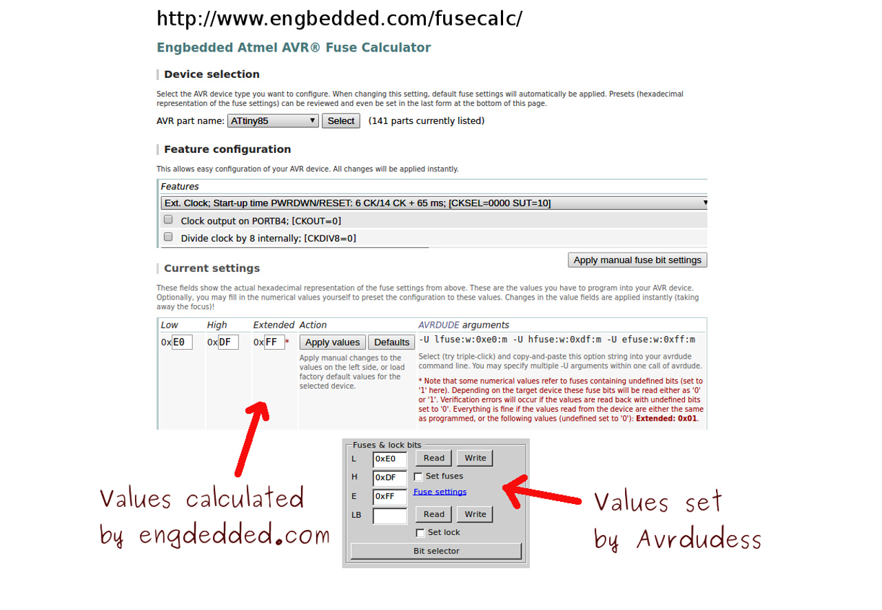
It's been quite a journey for me so far with the ATTiny13 - when they first arrived in the mailbox back in 2016 I fell about the place laughing at their physical size () and also their limitations in terms of processing power and memory.

But the price kept me coming back - in 2017 I could pick up 50 or so of these little fellas for around AU$18. Now in 2020 they are still a reasonable AU$25 or so. Originally I used the Arduino IDE and language with various cores available at the time to program them - but I did brick a few of them because I did not really understand fuses and other AVR dark arts.

A lot of reading and reading and reading later I learned about fuse setting and then made the switch to programming in assembler. I started to really enjoy the challenges and rewards of these chips with their perfect combination of price and power for most of my projects. They also slept real well when asked to, and used hardly any energy going about their business, particularly when I learned how to successfully run them at 128kHz.

Recently on this blog I wrote about an ATTiny13 project that included PWM and also "random" number generation. Before that I recently looked at the electronic components that maximise the energy use for the same project.

In both those blogs I glossed over the assembler programming bit, but I thought that it might be useful to spend a little bit of time looking at the code working at the bare metal level through the lens of Gerhard Schmidt's amazing AVR simulator

At the heart of the blog today (and video) is a focus on the values in the registers of the AVR while the program is stepping through each assembler instruction. A couple of years ago I didn't really understand what a "register" was, and I would have given anything to "see" the registers in action. It is always more educative to link abstract and concrete - and using avr_sim in this way makes it possible.

Whilst I could spend hours stepping through the code today, I really wanted to concentrate on the random number generator, and also how the values are shifted around in the registers and manipulated by the code.

This is probably not the best way to write AVR assembler, but the teacher in me says that it might be easily understandable for a beginner. The useful part I believe is the ability to repeat the video a few times and keep an eye on different register values while at the same time matching up the assembler instructions.

Even better - download avr_sim, load the code into the simulator and step through each command yourself to watch it tick over "in real life"!


Saturday, May 23, 2020

0000 0000 0011 0000

CD4093 - the magnetic alarm thingy Part Two

On a quest to find some use for the CD4093 Quad Schmitt Trigger NAND gate IC (simply because I love inserting the phrase "Schmitt Trigger" into any conversation), I found in an earlier blog that the CD4093 chips that I had in the bucket did indeed work as advertised. Now it was time to employ it in a circuit that I had found a few months ago online.


So many Schmitt Triggers

One immediate snag that I did not anticipate was the small matter of not having any prescribed MH183 Hall Effect sensors in the buckets. I did scramble around and dig out the following sensors:

  1. SS49E - providing an analog output related to the strength AND direction of the magnetic field - lovely!
  1. US1881 - which outputs a digital signal, and
  1. A3144 - which also outputs a digital signal.
Three sensors ready for testing
The question is do these work? Also, which of them is closest to the MH183? Well the MH183 is billed as a digital output sensor, and from the datasheet we read "The output transistor will be switched on in the presence of a sufficiently strong South pole magnetic field facing the marked side of the package. Similarly, the output will be switched off in the presence of a weaker South field and remain off with “0” field."

After matching this description with the sensors in the bucket and doing a little experimentation (see video below, and note that a 10kΩ resistor needs to be added across 5V and output for the US1881 and the A3144)), I decided that the A3144 would be a suitable replacement. See below for their block diagrams from their respective datasheets - very similar!


If the sensor provides such a clean digital signal, then I started to wonder why should I bother to have any of the extra circuitry? Well it turns out that the 10kΩ resistor means the current allowed out is minimal, plus you can see from the video when I tried this (with a 1kΩ resistor, *yikes* wasted current) that there was no hysteresis, which is the whole point of using a Schmitt Trigger IC in the first place.

So basically we need to invert the signal and clean it up a bit so that the LED/ALARM is OFF if the door/window is closed, then tripped ON if the magnetic connection is broken. The circuit at 6.0V consumes 5.2mA doing nothing, and around 10.3mA once the alarm has been tripped - so that is pretty awful if you want to run this off a battery.


The CD4013 circuit hooked up and ready for magnetic action
There are more efficient ways - and in fact I think I'll build something with a sleeping μC, although there may be no getting around the fact that a Hall Effect Sensor is using current just doing nothing. There are low quiescent current Hall Effect sensors, but the price tag is pitched above my interest.

When I did eventually reach into the buckets to find a commercial "Hall Effect Sensor Module" it turned out that it also used the A3144 sensor at it's heart, and then an LM393 comparator and some other parts to provide the digital output. Crazily, the module uses about 6.5mA when not active, but with the yellow LED I plugged in to indicate loss of magnetic field it used 5.3mA when active - now that's OpAmp magic for you.

The commercial version with a comparator


Saturday, May 16, 2020

0000 0000 0010 1111

CD4093 - Part One (Finally...maybe...)

I love a good Schmitt Trigger IC (well, who doesn't?), but I had no fun at all when I tried to make a circuit using the CD4093 Quad Schmitt Trigger IC configured as a "mains" power detector, as documented on a previous blog.

It was a disaster, and the whole blog ended up being about the ever reliable CD4017 standing in and actually working as a mains detector. Now, with some experience but also some trepidation I return to the CD4093, firstly as a legitimate one shot Schmitt Trigger NAND gate, and then maybe as a magnetic window/door alarm thingy. If I end up using the CD4017 again for this project, I promise not to mention the CD4093 ever again!

The first order of business is to plug in a chip and make sure it's not full of little socks (long story) and then configure one of the NAND gates available to act as a Schmitt trigger (in this case to set the sensitivity of a light dependent resistor). Note that all other inputs on the other three NAND gates are pulled high (or low) as recommended, although in quick testing I abandoned that for brevity.


Adjusting the trimpot (10k linked with 1k fixed) to make a voltage divider with the LDR will adjust for sensitivity of the circuit making it trigger depending on different ambient light.


The circuit I have in mind for the quad-NAND gate IC needs all four gates, so I set about testing all four. In the first chip tested, pins 4/5/6 didn't work! I swapped the miscreant out for another chip from the same batch and...pins 4/5/6 failed. Was the whole consignment on the nose? I dug into a bucket and found a CD4093 from another supplier and after testing found that...pins 4/5/6 were duds! What?

Mmmm, finally I twigged and changed the ultra-cheap "Mr Crappy" breadboard for another ultra-cheap breadboard (thanks Ben Eater "not all breadboards are the same") and then success, as all four NAND gates on all three chips tested fine and as expected (see video below). The next step will be to hook up the hall effect sensor etc., and then maybe in Part Two of this blog we might finally see a successful CD4093 project and my faith in Schmitt Triggers will be restored.


Saturday, May 9, 2020

0000 0000 0010 1110

OLED clock via ATTiny85 and External 1MHz Timer

A couple of blogs ago I was fiddling with a 1MHz active crystal oscillator. After establishing that it wasn't full of tiny socks (long story), and also that it seemed pretty accurate, I hooked up the timer to an ATTiny85 to...er...blink an RGB LED.

I did say in that blog that I would endeavour to use this external timing source to maybe make some sort of clock. The exact words were "I think that I will test this signal with a display to give the time of day, and check it periodically to see if it drifts over days/weeks."

The first decision then is how do I output the time? I have already done this with other processors using a TM1637 7-segment display module (works great), plus some other 7-segment options, but I have never played in the sandpit with an OLED display.

They look pretty cool and all of my reading seems to point to the fact that they are easy-ish to get up and running. I did have some blue 128x32 OLEDs in the bucket, so I ripped one out and onto the breadboard it went.

Now for some libraries. As I am using an ATTiny85, I'll either need to spend a few weeks nutting over the datasheet and learning way too much about I2C, time keeping and oled-ing, or borrow someone else's brain via libraries written for this little microcontroller. I chose the latter! There are a few good libraries around, but in the end I settled on the following:


#include <TinyI2CMaster.h>  // https://github.com/technoblogy/tiny-i2c
#include <Tiny4kOLED.h>     // https://github.com/datacute/Tiny4kOLED
#include <TimeLib.h>        // https://github.com/PaulStoffregen/Time

The next step was to write a heap of code with the following flow...
  1. Display the time
  2. Listen for button
  3. If button pushed, set the time
  4. Display the time
One disconcerting and unexpected problem came up when I went to use PB4 (PCINT4 or pin3) as a button input to facilitate time setting. It didn't work! As a quick workaround I wrote the code to set the clock using only one button (which worked fine, even if it was a bit clunky), but I was still puzzled why pin3 "disappeared" as an option for a GPIO, even though there was nothing actually connected to the pin.

Days of rumination followed and in the end I dove deep into the ATTiny85 datasheet (OK, it was only page 26) where it is stated that for a single external clock source "the CKSEL Fuses must be programmed to 00”.

If I was reading it correctly then this would change the fuse settings from what I did last time (external crystal oscillator requiring both XTAL1/pin2 and XTAL2/pin3) to an external clock source only requiring one pin (CLK1/pin2). Heading over to the amazing AVR Fuse setting calculator site I saw that you could indeed set the fuses for an external clock signal, not just external crystal oscillator.


Initially I set the fuses using Avrdudess, which worked fine - but I wanted to see if I could modify the "boards.txt" file in Spence Konde's ATTinycore so that both fuse setting and hex file uploading might be possible from the Arduino IDE. I modified the fuse settings from the above calculation (LOW: 0xE0, HIGH: 0xDF) in the file as follows:
...<drumroll>...and it worked great! I could now both select the external timer source and program the ATTiny85 to be a clock from the Arduino IDE.

Here is the full code, and here is the programmer/clock on the breadboard.


Saturday, May 2, 2020

0000 0000 0010 1101

Charlieplexing all those lights

In an earlier blog I looked at extending the miserly 5 available GPIO pins on an ATTiny13 to drive 8 LEDs using a 74HC595 shift register IC. At the time I mentioned a possible alternative charlieplexing solution and how it might be "fun" to try to drive more LEDs than the pins would nominally allow.

The target for full charlieplexing is N*(N-1) lights from N pins. I thought that I would start with 4 pins and therefore 4*3=12 LEDS. It was very confusing and ended up a bit of a mess (although it did work!). Eventually I sat down with a tablet and sketched out a logical representation of the desired circuit.
Oh yeah, that makes so much more sense!

Sure, it looks great (?) but then I need to arrange the LEDs in a line so that addressing them in some meaningful way is possible. The next Frankenstein diagram was a possible rearrangement as follows:
Wiring courtesy of a local starling

I wondered for a brief moment if there was a more efficient way to wire this up (there is), but to be honest I thought I could spend WAY too much time optimising the circuitry and not enough time soldering and looking at the blinking lights. And isn't that the fun part?

The ATTiny13 pins are labelled 1-4 on the diagram above which is shorthand for PB1-PB4. I chose these specific pins because when they are in use (e.g. as outputs in this case), and in consultation with the datasheet, they all line up in a row nicely:


DDRB = 0b00011110


Writing the code was then much simpler than my earlier efforts and using the diagram above as a guide (full code available on github), I was able to map the code to the circuit in a more logical way. The final code (in Arduino "C") uses 902 bytes, 88% of the available program storage space on that tiny guy. It runs five different effects with a bit of gap, then loops back indefinitely.

The LEDs are addressed in a 12x2 array (12 leds with 2 properties, port direction and port state) and after settling on that arrangement I just needed to write some loopy loops to access each LED.

If I needed one LED lit then it was easy, but for two or more LEDs the program needs to oscillate between them so quickly that the human eye/brain combo believes that they are both continuously lit

In the video below I focus on lighting LED "h" (the eighth LED from the right) which needs PB1 and PB3 set to OUTPUT, and a port state of HIGH for PB3 and LOW for PB1.

DDRB = 0b00001010
PORTB = 0b00001000


You can see this exact pattern described in the array shown in the code below labelled "LED h". There were a couple of other small bits in the code that you might find interesting, and it is all commented if you wish to take a deeper dive.

const byte leds12 [12][2] =

{
    {0b00000110, 0b00000010}, // LED a
    {0b00000110, 0b00000100}, // LED b
    {0b00001100, 0b00000100}, // LED c
    {0b00001100, 0b00001000}, // LED d
    {0b00011000, 0b00001000}, // LED e
    {0b00011000, 0b00010000}, // LED f
    {0b00001010, 0b00000010}, // LED g
    {0b00001010, 0b00001000}, // LED h
    {0b00010100, 0b00000100}, // LED i
    {0b00010100, 0b00010000}, // LED j
    {0b00010010, 0b00000010}, // LED k
    {0b00010010, 0b00010000}, // LED l
};

void lightemup (byte portdirection, byte portstate, int mydelay) {
    DDRB = portdirection;
    PORTB = portstate;
    delay(mydelay);

}

lightemup(leds12[0][0], leds12[0][1], 50);

The end result looks a bit of a mess on a breadboard...


...but blinks real nice. Note that the purists might see that I have rotated the ATTiny13 180 degrees from the diagrams above - I was under the illusion that might make the final wiring easier but I'm not sure that is true!