Friday, June 24, 2022

0000 0000 1001 1011

Timing Gates for Racing Cars

Being a teacher can be an interesting gig. One day you're out on the oval in freezing slush, separating overly enthusiastic teenagers intent on wrestling one another into submission and wondering where your life went astray. 

Then some days you will have an experience of sublime excellence in your chosen field (mathematics natch), be complimented by a parent, be paid to go to a wonderful concert, and leave work early because you can.

It's the proverbial box of chocolates!

A couple of weeks ago I was asked to help out on a STEM project where CO₂ gas-powered model cars are fired along a wire to test student design. 

In the past the "runs" were measured using manual techniques such as a stopwatch.

We can improve the accuracy of the timing using a laser gate - a laser light shines into a photodiode. When the light is shining, there is a voltage generated. When there is no light, this voltage drops.

The difference can be used to see when a laser beam is interrupted, in this case by a toy car!

The photodiode is connected reversed biased with VCC to cathode and the anode via a resistor to ground. If light falls on the diode it will cause a current through the resistor, which will cause a voltage across it.


You can choose the sensitivity by varying the value for the resistor, or indeed putting in a variable resistor for sensitivity.

There needs to be enough voltage drop across the photodiode to measure.

The following code is a skeleton for the students to work with, but it demonstrates how such a circuit can be used to capture start and stop times for this project.

/*
  Timing gate using laser diodes as transmitters and photodiodes as
  receivers.
  25 May 2022
*/

const int startPin = A0;    // starting receiver
const int stopPin = A1;     // stopping receiver

int sensorValue = 0;        // value read from the photodiode
int outputValue = 0;        // scaled value

long gotime = 0;            // timing variables used by
long stoptime = 0;          // millis()
long racetime = 0;

float printtime = 0;        // converted for display

byte ambient = 50;          // can use this or a 10k pot in
                            // circuit to adjust for ambient light

void setup() {
  Serial.begin(9600);
  Serial.println("RACING: ");
  delay(500);               // settle time before race
}

void loop() {

  sensorValue = analogRead(startPin);
  outputValue = map(sensorValue, 0, 1023, 0, 100);

  if ((outputValue > ambient)) {
    gotime = millis();        // and we're racing
    Serial.println("GO!");
    delay(500);               // delay while end of car goes past start gate

    sensorValue = analogRead(startPin);
    outputValue = map(sensorValue, 0, 1023, 0, 100);
    delay(2);                 // ADC convert time delay

    while (outputValue < ambient) {

      sensorValue = analogRead(startPin);
      outputValue = map(sensorValue, 0, 1023, 0, 100);
      delay(2);               // keep reading
    }
    stoptime = millis();      // and we've finished
    Serial.println("STOP!");
    racetime = stoptime - gotime;
    printtime = racetime / 1000.0;
    Serial.print("Racetime: ");
    Serial.print(printtime, 3);
    Serial.println(" seconds");
    Serial.println();
    Serial.println();
    delay(5000);              // delay until next race possible
    Serial.println("RACING: ");
  }
  delay(2);
}

That all works fine, but some fine tuning (due to OH&S considerations) has seen the laser swapped out for an ordinary LED so the kiddies don't burn out their eyeballs staring too long at the pretty red light!

In the video below I use a straw hat LED which actually has quite a wide throw, so perhaps another LED or indeed the proposed glass/aluminium "tunnel" which should focus the light better.

It doesn't really matter as the sensitivity can either be adjusted in the circuit (via R), or in the code (via the variable "ambient").

I'm now handing this all over to the students and their teachers for the next stage - they need to do some of the development work, right?



Saturday, June 18, 2022

0000 0000 1001 1010

Mailbag #15

I was caught up a bit in the lovely arrivals this week, so there is a fair bit of faffing about - particularly with a "fake" CCTV camera!

The option to put an ESP32 CAM module inside a realistic looking fake is hilarious. In the meantime a random blinking guy is keeping watch over all the buckets of goodies - but where is the real cam? ðŸ˜‰


Friday, June 10, 2022

0000 0000 1001 1001

Pimping the ESP32-CAM

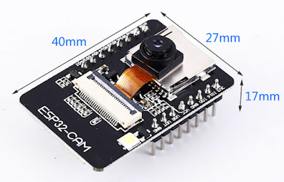
The ESP-32 CAM module is a pretty good (and usually cheap) bit of kit. I've used them about the place at times because they are quick and easy to setup.


Recently during a blog and video about a 3D print I mentioned en passant that I use an ESP32 which has been "pimped" to include control over the bright onboard LED. Plus I wanted better performance and some other features.

Note that I use Linux exclusively - I imagine that the process is pretty similar with Windows except for the multiple reboots required when Windows installs software!

In this blog and video I'm going to cover:

1. Programming the ESP-32 Cam module (connections/IDE/etc)

In the past I have programmed this module just using an Arduino and a few wires. The connections are simple and it works fine with the ESP32 CAM sitting on a breadboard.

The Arduino is programmed as "ArduinoISP", a sketch found in the examples menu of the Arduino IDE.


An alternative would be to use a programming module such as the following.


Unfortunately due to my filing system I am unable to find my version of this module, so in the meantime I decided to build my own with a generic Arduino shield PCB ordered years ago!


In the video I show a rudimentary version of this shield with the minimum VCC/GND connections, TX/RX and a button between GND and IO0 to put the ESP32 CAM into programming mode.


The ESP32-CAM board files for the Arduino IDE can be found here:


...or you can simply go to the Arduino preferences and copy and paste the following:

https://raw.githubusercontent.com/espressif/arduino-esp32/gh-pages/package_esp32_index.json

...as per this picture...


Then when you go to "tools", "boards" and "board manager" you can do a search for ESP32 and install the package as shown.


To test the rig I simply programmed up a couple of blinky sketches, in particular accessing the onboard LED (GPIO4) on the module - an important feature for lighting the scene.

NOTE: to program the board the button must be pressed to bring GPIO0 to GND and allow the ESP32 to be programmed, then after pressing the button again to release the connection and resetting the module, the blinking goodness shall begin!

void setup() {
  pinMode(4, OUTPUT);
}

void loop() {
  digitalWrite(4, HIGH);
  delay(100); 
  digitalWrite(4, LOW);
  delay(2000);
}

2. Uploading and running the "standard" software

When you are ready to access the camera, select the ESP32 CAM board as shown:


Then select the camera web server example as shown:


After you have changed the WiFi SSID and Password in the code and uploaded, you will need "unpress" the programming button, reset the device and then find it on your local network (e.g. by checking with your router, or using a piece of software such as nmap).

Once you have found your device you simply start a browser on the network and then type the address into the address bar.


The standard interface is fine and runs OK, but I wanted to trim up the code a bit (I didn't really need facial recognition for 3D printing!) and mainly I wanted access to the onboard LED.

So I started looking for alternative camera web servers.

3. Sourcing and uploading alternative software

I tested a few different versions of the web server until I found the right one for me, which turned out to be the following:


When you download the github code you can unzip it into a folder. Navigating to the "binarys" folder you can then upload the binaries to your ESP32 camera using the following command (also found in that directory in the "flashing.txt" file), again making sure that the device is in programming mode by pressing the button and resetting.

esptool.py --chip esp32 --port "/dev/ttyUSB0" --baud 921600 --before "default_reset" --after "hard_reset" write_flash -z --flash_mode "dio" --flash_freq "80m" --flash_size detect 0x1000 bootloader.bin 0x10000 espcam.bin 0x8000 partitions.bin

Unlike the standard web server version, you will need to make serial contact with the device e.g. via putty, press the space bar within 2 seconds of resetting it, and then enter your WiFi credentials for storage on the ESP32.


But once you're there, the interface is worth it!


4. Compiling and installing alternative software

The final phase (if you think it necessary, and you're more than a bit nerdy) is to compile the binary files yourself. To do this, follow the steps below:

a) download the esp-idf from github, and follow the instructions to install the development software
b) change directory to where the Makefile is for the ESP32-CAM software
c) type "source /path-to-esp-idf/export.sh"
d) "make" then upload binaries as before, or
e) "make flash" to both make and upload binaries to your ESP32-CAM

That's it!


Thursday, June 2, 2022

0000 0000 1001 1000

LGT8F328P fakers

The clone of the AVR/MicroChip ATMega328 microcontroller IC by Logic Green is another sign that Chinese manufacturers are stepping up their game.

The LGT8F328P is a handy (and cheaper) alternative to it's ATMega328 antecedent and boasts a faster processing speed 32MHz vs 20MHz.

I have tried these processors before, but only somewhat unsuccessfully in some type of NRF24L01 FrankenNano module featured in a previous video and blog.


But cursed as I am to pursue non-standard non-useful tech, I found myself in reception of a couple of "legitimate" fakes - the famous forbidden green modules.


This prompted me to explore the FrankenNano again - and to save you all the trouble, they really are just too much trouble!