Saturday, June 26, 2021

0000 0000 0110 0111

25Q32FVSIG FLASH MEMORY

At some point in an Arduino Journey you might lament the "tiny" amount of non-volatile memory (1024 bytes) found on the board. Some projects require data storage such that the data doesn't disappear when the power does!

The use of an SD-card module is possible, but I did see this little PCB on David Johnson-Davies most excellent Technoblogy site a few years ago.

The mastery of this PCB is the ability to plug straight in to a standard Arduino Uno and then be used, for example, as a data logger. For instance if you are doing long-term environmental monitoring then you could set up the project along the following lines:


I have done some of this type of work before (and used a connection to the internet to store the data), but lately it's all been about candles and so I have decided to demonstrate this little wonder board by sampling the output of an actual "flame-driven, likely to get burnt and torch the house, turn off the fire alarm, warn the neighbours, saddle the horses just in case" candle. 

Then, if successful in capturing the data, I could try running the output through an LED to see if the real life random brightness oscillations can be reproduced. 

Here is David's code, modified to include the input of a "button" (I just plug it into VCC or GND). If the button is HIGH then the code is set to capture data and if the button is LOW then we output via PWM to the LED.

/*
   Uses David Johnson-Davies (Technoblogy) DataFlash project to collect
   candle lumens via an LDR and then pump out the random candle goodness
   to an LED depending on the state of a button

   OneCircuit Sunday 6 June  16:54:19 AEST 2021
   YT: https://www.youtube.com/channel/UCTm3eCrN6wk-Ozt9ymyKIIg/videos
   Blog:https://onecircuit.blogspot.com/

   David's site: http://www.technoblogy.com/show?2JMU

*/

const byte analogInPin = A0;      // pin for LDR
const byte buttonPin = 8;         // pin for button
const byte outputPin = 6;         // pin for LED
boolean buttonPressed = false;    // is the button pressed?
int sensorValue = 0;              // initialise sensor reading
byte outputValue = 0;             // initialise output

// change these to suit
const int sizeofbuffer = 1000;
const int numberofbuffers = 40;
byte readdelay = 5;

byte flamedata[sizeofbuffer];     // data stored in buffer first

// start of David's code
#define PAGEPROG      0x02
#define READSTATUS    0x05
#define READDATA      0x03
#define WRITEENABLE   0x06
#define CHIPERASE     0x60
#define READID        0x90

const byte sck = 13;
const byte miso = 12;
const byte mosi = 11;
const byte cs = 10;
const byte power = 9;

class DF {
  public:
    boolean Setup();
    void BeginRead(unsigned long addr);
    void BeginWrite(void);
    uint8_t ReadByte(void);
    void WriteByte(uint8_t data);
    void EndRead(void);
    void EndWrite(void);
  private:
    unsigned long addr;
    uint8_t Read(void);
    void Write(uint8_t);
    void Busy(void);
    void WriteEnable(void);
};

boolean DF::Setup () {
  uint8_t manID, devID;
  pinMode(power, OUTPUT); digitalWrite(power, HIGH);
  digitalWrite(cs, HIGH); pinMode(cs, OUTPUT);
  pinMode(sck, OUTPUT);
  pinMode(mosi, OUTPUT);
  pinMode(miso, INPUT);
  digitalWrite(sck, LOW); digitalWrite(mosi, HIGH);
  delay(1);
  digitalWrite(cs, LOW);
  delay(100);
  Write(READID); Write(0); Write(0); Write(0);
  manID = Read();
  devID = Read();
  digitalWrite(cs, HIGH);
  return (devID == 0x15); // Found correct device
}

void DF::Write (uint8_t data) {
  shiftOut(mosi, sck, MSBFIRST, data);
}

void DF::Busy () {
  digitalWrite(cs, 0);
  Write(READSTATUS);
  while (Read() & 1 != 0);
  digitalWrite(cs, 1);
}

void DF::WriteEnable () {
  digitalWrite(cs, 0);
  Write(WRITEENABLE);
  digitalWrite(cs, 1);
}

void DF::BeginRead (unsigned long start) {
  addr = start;
  Busy();
  digitalWrite(cs, 0);
  Write(READDATA);
  Write(addr >> 16);
  Write(addr >> 8);
  Write(addr);
}

uint8_t DF::Read () {
  return shiftIn(miso, sck, MSBFIRST);
}

void DF::EndRead(void) {
  digitalWrite(cs, 1);
}

void DF::BeginWrite () {
  addr = 0;
  Busy();
  // Erase DataFlash
  WriteEnable();
  digitalWrite(cs, 0);
  Write(CHIPERASE);
  digitalWrite(cs, 1);
  Busy();
}

uint8_t DF::ReadByte () {
  return Read();
}

void DF::WriteByte (uint8_t data) {
  // New page
  if ((addr & 0xFF) == 0) {
    digitalWrite(cs, 1);
    Busy();
    WriteEnable();
    digitalWrite(cs, 0);
    Write(PAGEPROG);
    Write(addr >> 16);
    Write(addr >> 8);
    Write(0);
  }
  Write(data);
  addr++;
}

void DF::EndWrite (void) {
  digitalWrite(cs, 1);
}

DF DataFlash;

// end of David's code

void setup() {

  // look for the DataFlash module
  Serial.begin(57600);
  while (!Serial);
  if (!DataFlash.Setup()) {
    Serial.println("DataFlash not found");
    for (;;);
  }

  // initialise pins
  pinMode(analogInPin, INPUT);
  pinMode(buttonPin, INPUT);
  pinMode(outputPin, OUTPUT);
  delay(2000);

  // are we collect data or output data?
  buttonPressed = digitalRead(buttonPin);
}

void loop() {

  // collect data
  if (buttonPressed) {
    digitalWrite(outputPin, LOW);
    Serial.println("Collecting and writing data:");
    DataFlash.BeginWrite();

    for (byte readings = 0; readings < numberofbuffers; readings++) {
      for (int writenum = 0; writenum < sizeofbuffer; writenum++) {
        sensorValue = analogRead(analogInPin);
        outputValue = map(sensorValue, 100, 900, 0, 230);   // change to suit candle/lighting/etc
        if ((outputValue < 5) or (outputValue > 240)) {     // clean up rough edges
          outputValue = 0;
        }
        flamedata[writenum] = outputValue;                  // write to buffer
        delay(readdelay);                                   // delay between readings
      }

      // now write buffer to DataFlash module
      for (int writenum = 0; writenum < sizeofbuffer; writenum++) {
        DataFlash.WriteByte(flamedata[writenum]);
      }
    }
    DataFlash.EndWrite(); // done writing
    while (1) {};         // just wait, could flash LED?
  }

  // output data to LED
  if (!buttonPressed) {
    while (1) {
      DataFlash.BeginRead(0);
      for (byte readings = 0; readings < numberofbuffers; readings++) {
        for (int writenum = 0; writenum < sizeofbuffer; writenum++) {
          byte thisdata = DataFlash.ReadByte();
          analogWrite(outputPin, thisdata);
          delay(readdelay);
        }
      }
      delay(10);
      DataFlash.EndRead();
      delay(10);
} } }

The code seems to work fine, but some real issues emerged with the construction of David's flash module.

1. I oven baked the first one with the worst application of solder paste seen since the great solder paste disaster of 1687 in Cornwall. The program reported "DataFlash not found".

2. The first couple of soldered modules also came back "DataFlash not found".

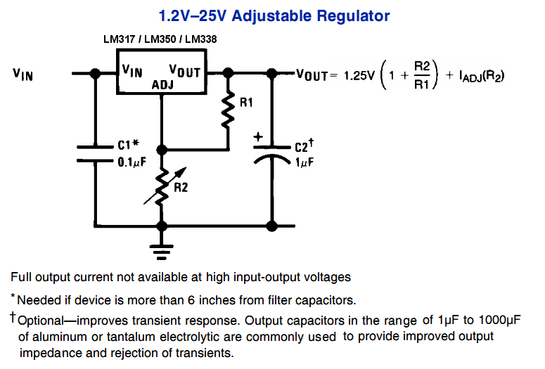
3. Several versions of 3.3V regulator needed to be tested until I found a couple of guys that worked as advertised.

4. Quite a few of the Winbond 25Q32FVSIG chips were either faulty or I fried them in the process - a separate blog will look at these chips - are they really dead?

5. The wackiest problem? The diodes linking the flash memory to the input/output as per David's circuit stops the whole shebang from working? I've indicated this below with menacing red circles.

In a fit of rage/genius I simply removed them. The modules then worked and the universe celebrated (well, I celebrated).


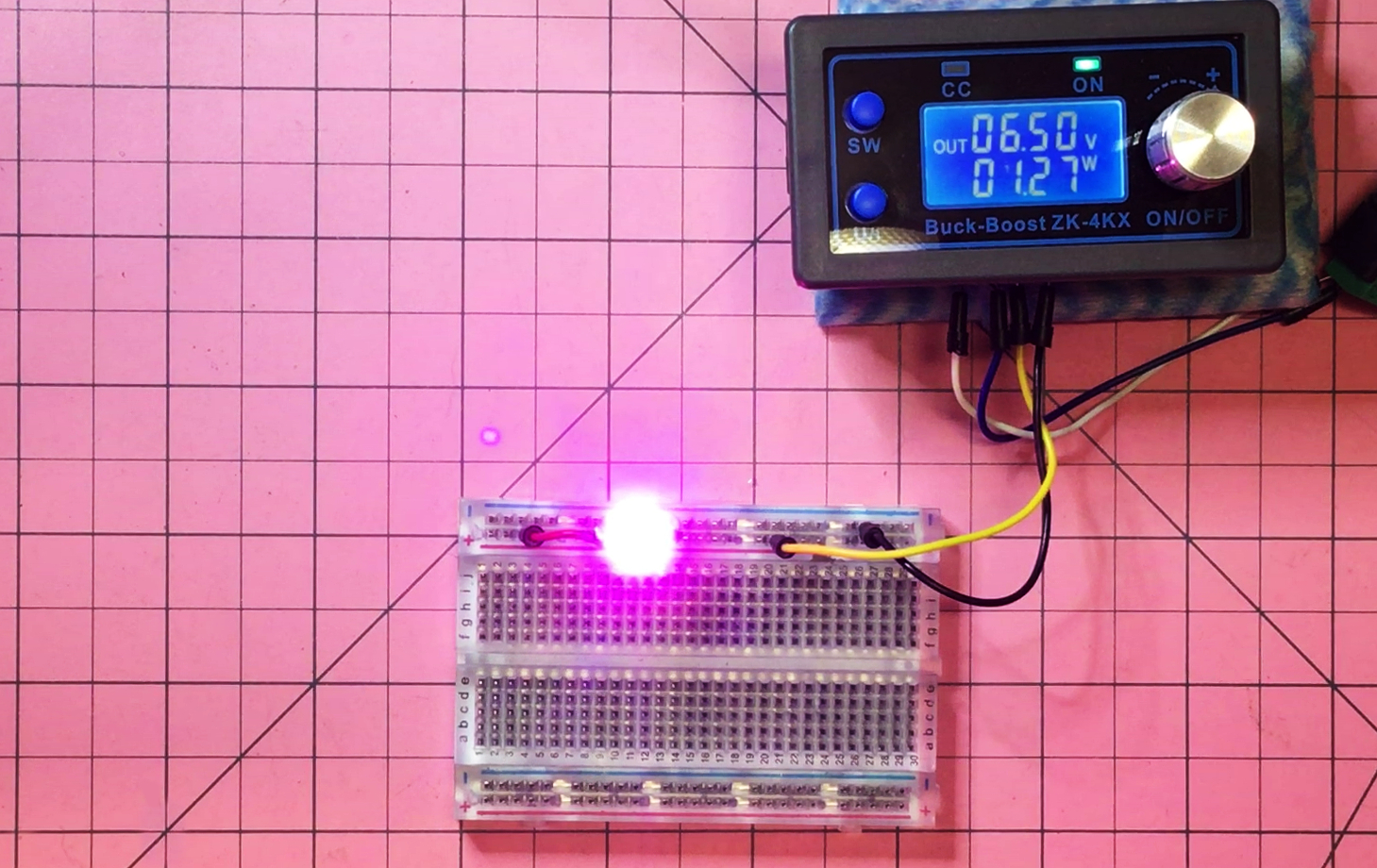
Net result? Four fully working 4Mb flash memory boards that can sit on the edge of the Arduino Uno doing it's thing and record data happily, then regurgitate it as required.

Things to try?

1. Check out the Flash Chip "failures" using an EEProm adapter and appropriate tester.

2. Use bigger capacity chips! I've got some 25Q64FVSIG (8Mb) and 25Q128FVSIG (16Mb) chips on the way.

3. Design my own (larger) board. Omit diodes?


Saturday, June 19, 2021

0000 0000 0110 0110

Mailbag #5, then Postbag #1

A few parcels arrived this week - it's interesting that prices have recently skyrocketed, as have freight charges, and so I've shut down a lot of my purchases to match.

The so-called "chipaggedon" has meant that some stock is not only not available anymore, but also I see that projected delivery times can be over a year. Naturally the prices are therefore ridiculous.

A couple of years ago I bought a dozen or so STM32 based "blue-pill" boards - which at the time were a cheap alternative to the Arduino Nano clones, even though they were more powerful. The price at the time was around AU$2 - now these alternatives are not so cost effective at around AU$13 (June 2021).

I also bought some "raw" STM32 chips for the Pesky Padauk Programming Project. Those chips (even if you could order them), have gone from around AU$1 in price to almost AU$10 per chip - ridiculous! I may end up de-soldering the non-starters so that I have supplies for the future.

In another slightly unnerving development I also had three orders in the last week cancelled by suppliers, with a 24-hour turnaround on refund, making me think that perhaps there were empty shelves in the warehouse to start with?

Perhaps we'll all be frantically de-soldering in the next couple of years to recover/recycle what we can? Luckily all of my "dead" projects end up in the Bucket of Shame™, and so I have a bit of a graveyard from which to rob!

In the meantime, here is some overpriced useless stuff that not only did I manage to buy, but it actually arrived! In a break from previous form I haven't put any links in because I cannot vouch for the availability of these products in the current climate. 


Saturday, June 12, 2021

0000 0000 0110 0101

LM338 (PSU III)

The next phase of the PSU project sees me kicking out the LM7805 as the linear voltage regulator component and swapping in the LM338, for the following reasons.

1. The LM7805 is maxes out at 1.5A whereas the LM338 is rated to 5A (peaking at 7A)

2. My LM7805 stock seems a little shonky

3. I've used the LM338's cousin the LM317 quite a bit and I like the family

The LM338 regulates voltage according to this circuit from the datasheet: 

I have a billion different resistor values and was a bit concerned about choosing values which gave a Vout close to the target voltage. To ease my mind I coded a quick program in Python as follows:

from array import *

print("LM338 calculator")
Vout = float(input("Voltage out: "))
accuracy = float(input("Percentage accuracy? "))

ratio = Vout/1.25-1
accuracy = accuracy/100*ratio

r1 = array('f',[1, 1.5, 2.2, 2.7, 3.3, 3.9, 4.7, 5.1, 6.2, \
                6.8, 7.5, 8.2, 10, 12, 15, 18, 20, 22, 24, \
                27, 30, 33, 36, 39, 43, 51, 47, 56, 62, 68, \
                75, 82, 91, 100, 120, 150, 180, 200, 220, \
                240, 270, 300, 330, 360, 390, 430, 470, \
                510, 560, 620, 680, 750, 820, 910, 1000, \
                1200, 1500, 1800, 2000, 2200, 2400, 2700, \
                3000, 3300, 3900, 4300, 5100, 6200, 7500, \
                9100, 12000, 18000, 22000, 27000, 33000, \
                39000, 75000, 82000, 56000, 62000, 3600, \
                4700, 5600, 6800, 8200, 10000, 15000, \
                20000, 24000, 30000, 36000, 43000, 47000, \
                51000, 68000, 91000, 100000, 120000, \
                150000, 180000, 200000, 220000, 240000, \
                270000, 300000, 330000, 360000, 390000, \
                430000, 470000, 510000, 560000, 620000, \
                680000, 750000, 820000, 910000, 1000000])

r2 = array('f',[1, 1.5, 2.2, 2.7, 3.3, 3.9, 4.7, 5.1, 6.2, \
                6.8, 7.5, 8.2, 10, 12, 15, 18, 20, 22, 24, \
                27, 30, 33, 36, 39, 43, 51, 47, 56, 62, 68, \
                75, 82, 91, 100, 120, 150, 180, 200, 220, \
                240, 270, 300, 330, 360, 390, 430, 470, \
                510, 560, 620, 680, 750, 820, 910, 1000, \
                1200, 1500, 1800, 2000, 2200, 2400, 2700, \
                3000, 3300, 3900, 4300, 5100, 6200, 7500, \
                9100, 12000, 18000, 22000, 27000, 33000, \
                39000, 75000, 82000, 56000, 62000, 3600, \
                4700, 5600, 6800, 8200, 10000, 15000, \
                20000, 24000, 30000, 36000, 43000, 47000, \
                51000, 68000, 91000, 100000, 120000, \
                150000, 180000, 200000, 220000, 240000, \
                270000, 300000, 330000, 360000, 390000, \
                430000, 470000, 510000, 560000, 620000, \
                680000, 750000, 820000, 910000, 1000000])
for i in r1: for j in r2: if (j>i): division = j/i if (abs(division-ratio)<accuracy): print(round(j,1),"divided by",round(i,1), \ "gives", round(1.25*(1+j/i),2)," volts")


So for instance if I were to seek 9V from this list of possible resistor ratios to within an accuracy of 0.5% the output is as follows:

LM338 calculator
Voltage out: 9
Percentage accuracy? 0.5
6.2 divided by 1.0 gives 9.0 volts
51.0 divided by 8.2 gives 9.02 volts
62.0 divided by 10.0 gives 9.0 volts
510.0 divided by 82.0 gives 9.02 volts
620.0 divided by 100.0 gives 9.0 volts
5100.0 divided by 820.0 gives 9.02 volts
6200.0 divided by 1000.0 gives 9.0 volts
510000.0 divided by 82000.0 gives 9.02 volts
51000.0 divided by 8200.0 gives 9.02 volts
62000.0 divided by 10000.0 gives 9.0 volts
620000.0 divided by 100000.0 gives 9.0 volts

Which means I might choose 620k for R2 and 100k for R1. So I set up two LM388's fed from the buck/boost converter to test the ratios, the circuit and also the indicator LEDs before committing to a 3D print run.

The unusually weird problem with this whole project has been the "tripping" of the power once the current creeps much above about 125mA. It was so frustrating that I swapped out nearly every component excepting the obvious one ...


Saturday, June 5, 2021

0000 0000 0110 0100

Grow light or Fake Views?

Here in Tasmania (43°S) we can have awfully short growing days in winter. If you have a penchant for salad all year round, and you don't like paying stupidmarket prices, then you may wish to employ an artificial source of light in a growing medium and boost the watery sunlight by an hour or so. Even better if solar powered?!

One possible problem is the use of a narrow frequency light source - if you miss the spectrum that chlorophyll is expecting to do it's photosynthetic magic then no amount of shiny goodness is going to help!

Our own sun (Mr Sol) is pumping out the good ergs across the required visible spectrum as follows.

So clearly if we can match the "natural light" spectrum, or indeed just provide that which is needed by chlorophyll, then the power will not be wasted (e.g. in lost frequencies). There are many expensive commercial options for this type of project, with impressive published spectral analyses to match the price.


There are also international standards (of course) for regulated markets, but I'm not looking run a commercial hothouse, I just want to see if these type of LEDs are effective. 

So with coins in hand I pushed the button on 50 3W "Natural Spectrum" LEDs via my favourite supplier. After calculating an appropriate resistor for the circuit I flicked the switch - they're purple?


So have I just been sent single frequency (or narrow range) lights? The only way to tell is to fire up the spectrometer (yep, I have access to one of those babies) and to run some tests. The result? You be the judge: