ESP32 Driving a relay OTA
After recent arrivals in the ESP32 adapter and relay department I decided to put together a circuit that allows for remote switching of decent current (e.g. 10A).
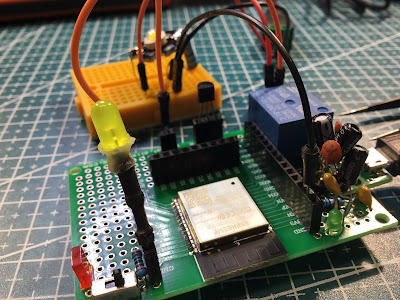
The circuit is similar to the one shown below (with the ESP32 playing the part of the switch):

The high signal drives the mosfet (a BS170) which opens the relay and releases all the ergs for the LED. Soldered up it looks quite good (don't look underneath), excepting that the 5V to 3.3V DC converter (SSP7603) looks a little ugly with all the capacitors stuck onto it like barnacles!
More or less standard OTA code makes this easy to program over the air, and I was pretty chuffed to be able to change the frequency of two separate GPIO pins without actually wiring up the ESP32 to a computer.
#include <WiFi.h>
#include <ESPmDNS.h>
#include <WiFiUdp.h>
#include <ArduinoOTA.h>

const char* ssid = "MyWifiConnection";
const char* password = "MyWifiPassword";
const char* host = "Blinky OTA32";
unsigned long ledtime = 0;
unsigned long relaytime = 0;
unsigned long currentMillis = 0;
unsigned long led_delay = 3000;
unsigned long relay_delay = 500;
boolean ledstate = false;
boolean relaystate = false;

#define led_pin 5
#define relay_pin 4

void setup() {
  pinMode(led_pin, OUTPUT);
  digitalWrite(led_pin, LOW);
  pinMode(relay_pin, OUTPUT);
  digitalWrite(relay_pin, LOW);

  WiFi.mode(WIFI_STA);
  WiFi.begin(ssid, password);

  while (WiFi.waitForConnectResult() != WL_CONNECTED)
  {
    // could put debug stuff in here
  }

  ArduinoOTA.setHostname(host);

  ArduinoOTA.onError([](ota_error_t error) {
    (void)error;
    ESP.restart();
  });

  ArduinoOTA.begin();

  // timing markers
  currentMillis = millis();
  ledtime = currentMillis;
  relaytime = currentMillis;

}

// loop() visits here for actual code
void dostuff() {

  // fake multi-tasking routines with blinking!
  currentMillis = millis();
  if (currentMillis - ledtime >= led_delay) {
    if (ledstate) {
      digitalWrite(led_pin, LOW);
      ledstate = false;
    }
    else {
      digitalWrite(led_pin, HIGH);
      ledstate = true;
    }
    ledtime = currentMillis;
  }
  if (currentMillis - relaytime >= relay_delay) {
    if (relaystate) {
      digitalWrite(relay_pin, LOW);
      relaystate = false;
    }
    else {
      digitalWrite(relay_pin, HIGH);
      relaystate = true;
    }
    relaytime = currentMillis;
  }
}

void loop() {
  ArduinoOTA.handle();
  dostuff();
}
Probably the only interesting thing about the code above is the use of millis() to fake multitask - I love that technique and it works really well on these devices.
On a smaller device (e.g. ATTiny13) I'd probably use interrupts and count the ticks to activate the GPIOs when a coded amount is reached. The ESP32 has a LOT of flash overhead though, so I took the lazy way this time!
I'm hoping I can continue to refine this idea and maybe use these guys around the place for remote sensing and control. Watch this space!
No comments:
Post a Comment