A couple of blogs ago I went big with the ATmega128A, but this week some ATmega8A-16AU chips arrived and I thought I'd test them to see if the AliExpress vendor "KELI Store" has good AVR mojo.
Like the ATmega128A ICs, this chip requires some upfront soldering to make it useful. I have, for some unknown reason, two sizes of QFP32 to DIP adapters, one wider than the other. Both versions are "interesting" to program as I had to solder up a homemade version using this circuit as a guide.
The core to program the chips comes from MCUdude and just works - nice! The resultant PCBs are breadboard friendly and easy programmable. What use all of these chips I'm not so sure - I guess in the end I think of it as research into my preferred AVR - which rests at the moment on the wonderfully useful Attiny13A and the Atmega88A (more on this little guy for a later blog).
I have billions of 1206 SMD parts which are less than useful given their size and infrequent use. Simultaneously I was finding sourcing an exact through hole part for protoyping to be quite frustrating. I did the usual things including:
organising all the components ordered into containers which then went into lidded bins - with one problem being that if I want a 100nF capacitor I have to look up the bin number and the container number on a spreadsheet and then hunt through to bring the prize back to the bench - a little awkward at times.
having a "common parts" container which houses those parts that crop up frequently in prototyping such as a green LED and a matching 220Ω resistor - with the double problem of firstly not having a, for instance, LM317 in the parts container (therefore see point 1 above), or spending 10 minutes with poor eyesight trying to dig out an appropriate resistor from the tangle.
using a flip lid storage box - which took half a day to fill up with resistors and then label appropriately only to find that I've only reached for the parts in this way a couple of times, and I'm not sure why.
Bins in bins - thorough but awkward
The "common parts" container
The tiny compartment method
So I was looking around for a solution to these (and other) problems, when I chanced upon an smd to dip adapter on the interwebs. I bought a few but they were 0805 size (which was fine, but most of my components in SMD are 1206 - eyesight!). So I looked hard for a 1206 version but all that I found seemed expensive given the simplicity of the board.
Chuffed with recent success making my own 555 timer PCB (and a few other projects), I threw a few ideas together on EasyEDA and then had JLCPCB pump them out to Tassie just before the twin brakes of Chinese New Year and COVID-19 slowed up delivery.
Arrival from China just before the gates closed
Half soldered after headers attached
With 1206 resistors attached
Forming a simple LED circuit - nice!
After triumphant testing (they're awesome) I decided that I needed to spread the joy so I've set up a Tindie shop if anyone else is interested in this way of prototyping. I'll chuck on a few other products (like the 555 PCB as a DIY kit) as soon as I can just to see if anyone else enjoys this sort of madness.
From early experiments blinking LEDs with an Arduino I started thinking about minimalist ATmega328 based projects (more on that later), then swapping out larger AVR chips for smaller versions - firstly using the amazing Attiny85 and eventually the small but surprisingly useful Attiny13a. But along the way I wondered what, if any, advantages lay with some of the larger AVR chips available. Late one night (and isn't that always the way) I spotted the ATmega128A on AliExpress, and foolishly went ahead and ordered a few based on the promises of the extensive datasheet.
Impressive Specs
Now that looks pintastic!
OK so the chips arrived and the first thing I noticed was how damn small the pins were and how I wouldn't be able to access any promised AVR goodness unless the chip was mounted properly. If access is possible somehow, then there was the small matter of a suitable connection to the computer and IDE to program the thing. So back to AliExpress for some SMD to DIP boards and a USBASP programmer, and then I had to build a specialist programming adapter for the USBASP to connect. Yeah, this was working out real well at this point, good decision!?
First we need to make connect to a DIP-ish style compatible adapter
Mmmm, probs need to clean that mess up at some stage
The Atmega128 mounted on the adapter and then into the programming shield
A couple of more hurdles remained. Firstly the Arduino IDE needed suitable board functionality to match the chip, and that came from the amazing MCUdude, with one wrinkle being that the upload had to be via the "upload using programmer" option on the sketch menu (hours of fun assuming the connection was faulty before I spotted that one). Finally I needed to work out how to address the chip using the correct pins - which was a bit of a head scratch until I worked out that in order to use the FADE sketch I should address only those pins marked PWM on the pinout (in my case PE3 or pin 5 on the chip or the third pin on the pinout).
/* Fade This example shows how to fade an LED on pin 9 using the analogWrite() function. The analogWrite() function uses PWM, so if you want to change the pin you're using, be sure to use another PWM capable pin. On most Arduino, the PWM pins are identified with a "~" sign, like ~3, ~5, ~6, ~9, ~10 and ~11. This example code is in the public domain. http://www.arduino.cc/en/Tutorial/Fade*/int led = PE3; // the PWM pin the LED is attached toint brightness =0; // how bright the LED isint fadeAmount =5; // how many points to fade the LED by// the setup routine runs once when you press reset:voidsetup() {
// declare pin 9 to be an output:
pinMode(led, OUTPUT);
}
// the loop routine runs over and over again forever:voidloop() {
// set the brightness of pin 9:
analogWrite(led, brightness);
// change the brightness for next time through the loop:
brightness = brightness + fadeAmount;
// reverse the direction of the fading at the ends of the fade:if (brightness <=0|| brightness >=255) {
fadeAmount =-fadeAmount;
}
// wait for 30 milliseconds to see the dimming effect
delay(30);
}
The overhead Arduino Nano: Sketch uses 1144 bytes (3%) of program storage space. Maximum is 30720 bytes. ATmega128A: Sketch uses 1530 bytes (1%) of program storage space. Maximum is 130048 bytes.
Which is all fine, but *WOW* that took a bit more mucking around than expected for the result. Fun? Of course! And now if I ever need a huge AVR with 53 GPIOs (!!) then I'm all good.
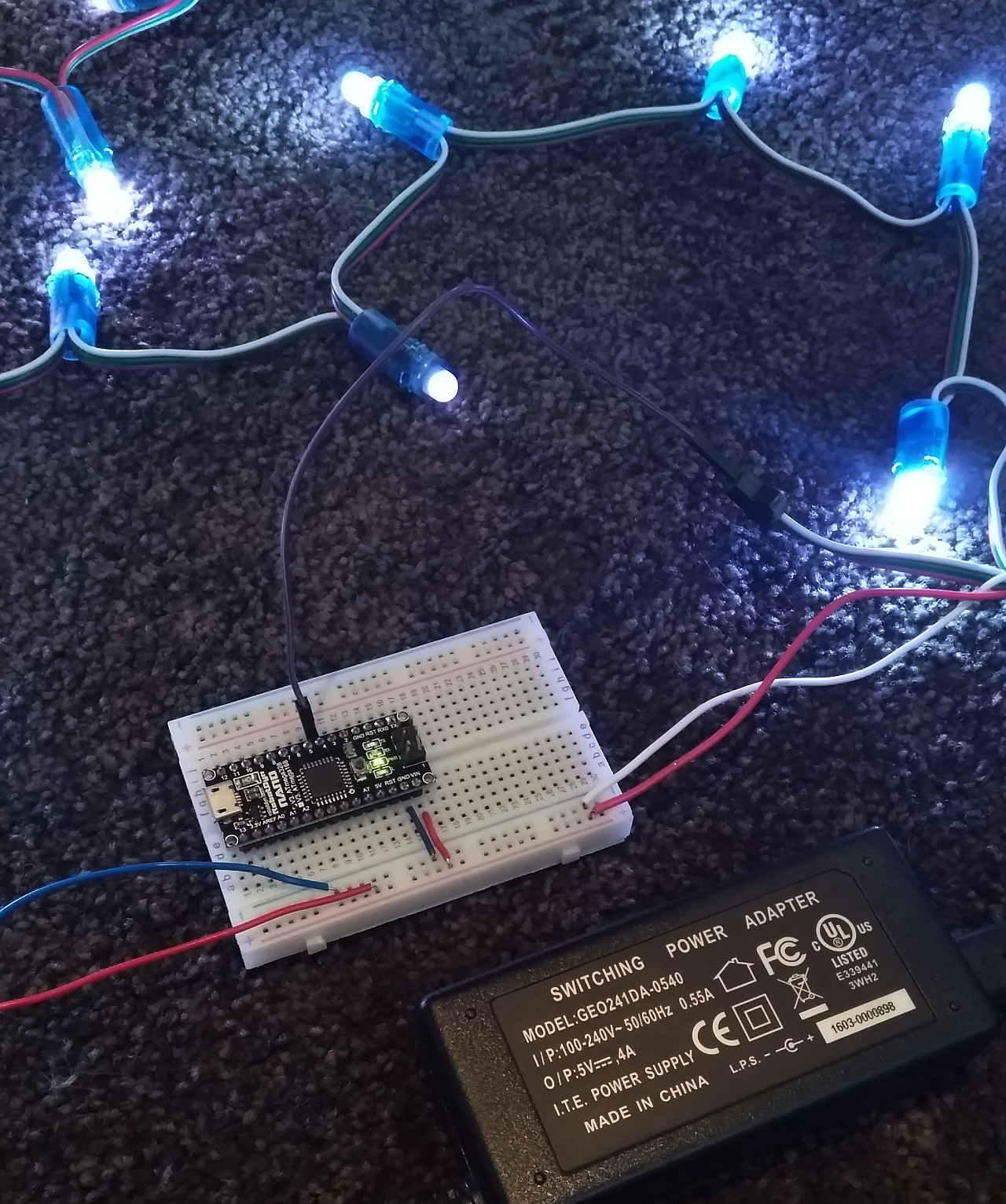
I have bought a few strings of LEDs for various purposes (some as yet undiscovered I suspect), but my latest favourite are strings of 50 individually addressable WS2811 12mm LEDs.
Lovely and relatively robust as well
With power coming in separately for greater current draw
There are a few ways of driving these guys, for example with a dedicated RGB controller, but I chose to use an Arduino Nano with a separate 5V power supply, and code based on the marvelous FastLed library.
If you squint you can see the chip inside!
There are a number of great demos that come with the package as well as some excellent code available on the interwebs. I grabbed a few likely ones and cobbled them together in this sketch. The lights arrived post Christmas this year, but the plan is to dive deep into the example code and come up with a suitably festive light show for this year. For the moment, here is the demo code in action (with some thought provoking (?) background music)...
I ran into a problem when testing (playing with) the 555 square wave signal generator. If I use small values for the capacitors (<100pf) and resistors (<2k), then the timer frequencies rise and I have a lot of trouble checking the output of the generator with my cheap DSO138 oscilloscope (limit 200kHz). The signal looks like it degrades and then disappears from about 50kHz onwards.
Mmmm...not much of a "square" wave at 50kHz
Yep, and all squares gone at 150kHz
I wanted to know if the obvious signal degradation at higher frequencies was a function of the oscilloscope or the signal generator itself, so I needed a way to "slow" the signal up to measure - like an electronic gear system. When searching online for solutions ("NO to a $500 oscilloscope!", says the budget-master) I found a couple of references to using a CD4017 decade counter. I have used this chip before and blogged about it already when I made a stupid clap switch circuit. In some configurations this chip is capable of frequency division, for example taking a clock input of 100Hz and dividing it by two to output 50Hz. It can maximum divide by a factor of 10 (pin 15 tied to ground), so I thought that at least I could "down shift" the signal by this amount and maybe get more sense from the oscilloscope. In the CD4017 datasheet there is actually a hint that you can "cascade" the counters and thus continue dividing by 10. So if I can link three such chips correctly, I could now lower the frequency by a factor of 10x10x10=1000, so a dodgy signal at 50kHz=50000Hz might perhaps be readable by my dumb 'scope at 50Hz.
The cascade shown in the datasheet seems like an overly complicated circuit with overflows, AND gates, etc. I thought that maybe all I really need to do is pump a signal from one CD4017 (divided by 10) into the input of the next chip as per the following circuit diagram.
The yellow wire is the signal from the 555 generator to pin 14 (clock, indicated with a blue LED), then each chip is powered by a red wire from VCC. Blue is GND, grey from GND to pin 13 (clock inhibit) will make the counter advance one at the positive edge of the clock signal. Orange from pin 15 (reset) tied to ground makes the IC divide by 10.
Finally, white from chip 1 (pin2 - output) to chip 2 (pin 14 - clock) and from chip 2 (pin 2 - output) to chip 3 (pin 14 - clock) provides each cascaded chip with the divided by 10 signal from the previous chip. I will test this version of a cascading signal divider with a lower frequency first, and then ramp it up and see what's happening at the higher frequencies.
I have a strong suspicion at the end of this investigation that the lovely square wave we can see on the screen at these higher frequencies is a result of monitoring the output of the CD4017 IC, which squares the signal off nicely, even if you feed it a sine wave (see the video). Maybe the signal generator output is genuinely "messy" at higher frequencies? So I guess to resolve this remaining question I will need to start campaigning to higher powers to fund a proper oscilloscope so that I can measure the direct output! In the meantime with the help of the CD4017 I can output a clean square wave at high frequencies from the 555 timer (indeed an opAmp or comparator would also be a solution to "squaring off" a messy signal). It is nice to know that I can make a fit for purpose clock signal - I think I'll feed it to an Attiny85 as an external clock just for fun at some stage.