I do a lot of teaching of "Electro-Technology", and nothing pleases me more than finding a treasure chest of potential projects to excite and educate the minds of the next generation. Case in point? David Johnson-Davies wonderful "Technoblogy" site. My students and I have built quite a few of these circuits and they continue to be popular.
The projects featured on David's site are wonderful in that they are carefully explained, have all the diagrams you would want, contain code if necessary and the resulting projects are both useful and work as designed. Actually, he's kind of my hero (along with Łukasz Podkalicki and his similarly inspiring ATTiny13 blog)!
One day when I'm a grown up I might buy a commercial function generator, but in the meantime this little guy looked amazing, and David made the PCB files available on github for those who wish to make their own. Yes please!
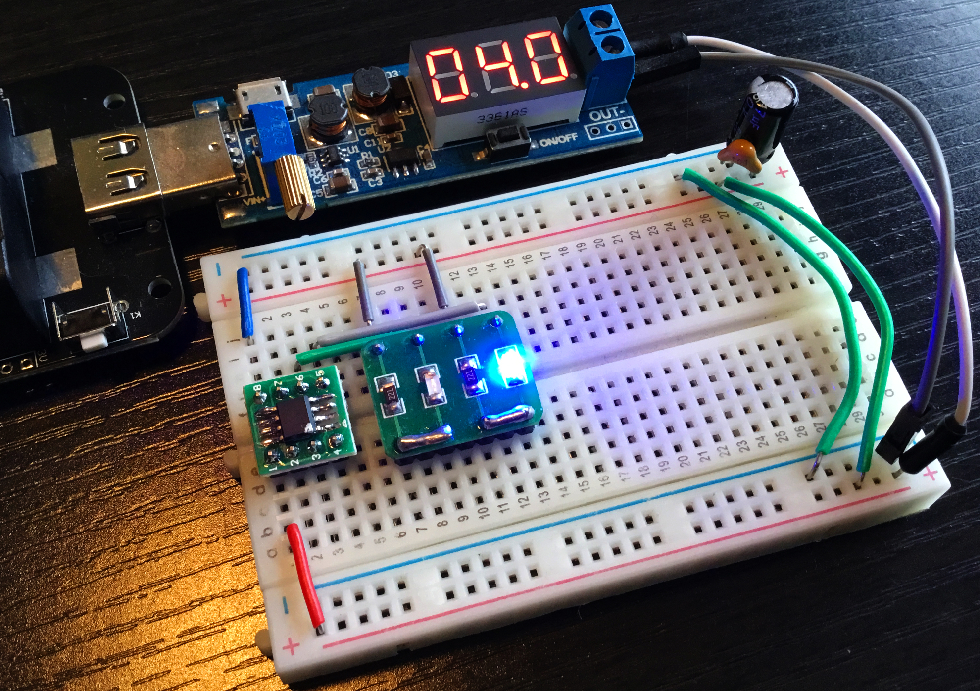
So I ordered a few and after they arrived I soldered one up and OMG it workedthe first try, and it was wonderful. Here is mine plugged in and with power.
And of course below is the video of the device being built and then actually working (er, after a little altercation with a couple of recalcitrant OLED displays).
I don't just use the Joule Thief circuits for running ATTiny13s as fake candles, as outlined in a previous blog post, but also they come in handy for providing "normal" light to illuminate the house at night.
In our house we don't tend to turn lights on at night as we move around - these little solar fellas sit on the floor and provide enough light to avoid tripping over giant dark puppies that habitually lie about the place in a haphazard manner.
We've been using the lights for more than a year now and they work really well, however I did spy some up-spec solar panels that looked a treat (a bit smaller and tidier) and as well they promised better performance via a higher current output at the same voltage (a promised 160mA vs 130mA at 2V).
Testing the panels side by side
So after flicking on both the soldering iron and hot-glue gun, I was up for tinkering away with the next generation of solar lights.
For a couple of years now I've been thinking about watchdogs - circuits or microcontrollers that watch/report on the circuit itself. For instance, some time ago I had an ESP8266 in my hothouse reporting temperature, humidity and atmospheric pressure every few minutes.
When the battery ran low, I lost data. So I have been looking at the possibility of enlisting an ATTiny13 (of course) to monitor the voltage in a circuit and then act at some minimum voltage threshold to, for instance, preserve data.
Coupled with that, I have been looking into EEProm storage on the ATTinys - so it seems that there may be an opportunity to combine the two as a "proof of concept". An ATTiny13 monitoring the overall voltage of the circuit, and an ATTiny85 storing data and perhaps shutting down when signalled by the "watchdog".
The code for the ATTiny85 is below. It just counts, and then when interrupted by the ATTiny13 it will display a "low battery" message, write the data to the EEProm and then shut down until the voltage/microcontroller is reset.
// ATTiny85 counts and if interrupted saves the count and then sleeps// OneCircuit Thursday 10 September 19:18:08 AEST 2020#include <EEPROM.h>#include <avr/sleep.h>#include <TM1637Display.h>// pins to talk to the TM1637 display#define CLK 2#define DIO 1int thisnumber =0; // counterint address =0; // eeprom addressvolatilebool LValarm =false; // has the voltage dropped? Set "no"// to make the word Low Battery in TM1637 speakconstuint8_t Lo_b[] = {
SEG_F | SEG_E | SEG_D, // L
SEG_G | SEG_E | SEG_D | SEG_C, // o
SEG_D, // _
SEG_F | SEG_G | SEG_E | SEG_C | SEG_D // b
};
TM1637Display display(CLK, DIO);
voidwritetheeeprom() {
EEPROM.put(address, thisnumber);
}
// Interrupt arrived from the ATTiny13!
ISR(PCINT0_vect) {
LValarm =true;
}
void setup() {
display.setBrightness(0x02);
EEPROM.get(address, thisnumber);
pinMode(PB3, INPUT);
ADCSRA &=~(1<< ADEN); // disable ADC (before power-off)
GIMSK =0b00100000; // turns on pin change interrupts
PCMSK =0b00001000; // turn on interrupts on pins PB3
sei(); // enables interrupts
}
void loop() {
// routine while voltage is OKwhile (!LValarm) {
thisnumber++;
if (thisnumber >9999) {
thisnumber =0;
}
display.showNumberDec(thisnumber, false);
delay(75);
}
// shutdown routine
writetheeeprom();
display.setSegments(Lo_b);
delay(10000);
display.clear();
set_sleep_mode(SLEEP_MODE_PWR_DOWN);
sleep_enable();
sleep_cpu(); // wake upon reset
}
The code for the ATTiny13 is below. It monitors the voltage, giving a visual clue (Green LED) if the voltage is above the threshold, and another (Red LED) if the voltage falls below.
// ATTiny13 monitors PB3 and sends a pulse out if voltage drops// OneCircuit Thursday 10 September 19:18:08 AEST 2020int vcc =0;
bool trigger85 =false;
int volt_threshold =850;
bool debug =false;
voidsetup() {
pinMode(PB1, OUTPUT);
pinMode(PB2, OUTPUT);
pinMode(PB4, INPUT_PULLUP);
pinMode(PB3, INPUT_PULLUP);
analogReference(INTERNAL); // use internal 1.1V as reference
delay(1000); // settle time
}
voidloop() {
vcc = analogRead(PB3);
// if voltage is OK and we haven't triggered, display greenwhile (vcc > volt_threshold &&!trigger85) {
vcc = analogRead(PB3);
digitalWrite(PB2, HIGH);
delay(50);
digitalWrite(PB2, LOW);
delay(2000);
}
// send the pulseif (!trigger85) {
pinMode(PB4, OUTPUT);
digitalWrite(PB4, HIGH);
delay(100);
digitalWrite(PB4, LOW);
delay(10);
trigger85 =true;
}
// red lights
digitalWrite(PB1, HIGH);
delay(50);
digitalWrite(PB1, LOW);
delay(2000);
}
It works great and you can see the result in the video below.
Not content with a simple LM358 square wave generator as seen on the last blog, I look this week at converting the square wave to other wave forms using the mathematical functionality of OpAmps. Casting about in the shallow end of the internet pool, I happened upon this variation of the previous circuit.
After lots of playing about on iCircuit and some deeper internet trawling, I was able to make the circuit work on a simulator as follows.
It was a little concerning that the signal degrades in voltage over the three opAmps, such that the final voltage fluctuation is only around 2V from a 9V supply. I tried to rope in a transistor to amplify (with no real success) but I'll keep trying to amplify the signal - probably with the "free" side of the second opAmp maybe something like the following:
The final (simplified) design, using only 10k resistors and 10uF capacitors, looks a treat "In Real Life™" and it functions (pun intended) as designed!
Slightly obsessed with the idea of a square wave oscillator as a timer, I have found many circuits which use an OpAmp to generate a square wave. Having tried a few, I settled on the LM358 datasheet version (p. 17, Figure 27) as follows.
There's a nice explanation of the theory and calculations for this type of circuit found on this site. Rather than the values for R1 etc,. shown in the datasheet, however, I used the following slight variation.
The changes were made mainly so that I could vary the oscillations (R4), and also I added an LED because if it's not blinking then it's not really electronics...
Here it is "in the flesh", and the video contains the all important blinking stuff.
After tens of hours of tears, sweat and the odd expletive - the fourth version I attempted actually worked. So now I take a closer look at the programming of these little chips.
It's worth noting that the toolchain for the factory supported IDE is entirely different to the open source version, and at this stage it seems you must choose one or the other.
With that in mind, I firstly installed dfu-util, and using the following code was able to successfully install the programming firmware onto the STM32 as per the instructions.
dfu-util -d 0483:df11 -a "@Internal Flash /0x08000000/064*0002Kg" \
   --dfuse-address 0x08000000 -D EASYPDKPROG.dfu

   dfu-util 0.9
   ...
   Opening DFU capable USB device...
   ID 0483:df11
   Run-time device DFU version 011a
   Claiming USB DFU Interface...
   Setting Alternate Setting #0 ...
   Determining device status: state = dfuERROR, status = 10
   dfuERROR, clearing status
   Determining device status: state = dfuIDLE, status = 0
   dfuIDLE, continuing
   DFU mode device DFU version 011a
   Device returned transfer size 2048
   DfuSe interface name: "Internal Flash  "
   Downloading to address = 0x08000000, size = 29068
   Download  [=========================] 100%        29068 bytes
   Download done.
   File downloaded successfully
All went smoothly and so next it was a tough choice to select the first guinea pig IC. I think that of all the Padauk chips that I have ordered, the one showing the most potential for the types of projects that I like to get involved with is the PFS154-S08 available from LCSC.
Into the cradle went the chip and then I wanted a simple method of checking if the programming side of things worked. The obvious choice was of course a blinking LED - the "Hello World" of microcontroller programming.
/* BlinkLEDs Flicks on and off two LEDs attached to PA4 and PA3 of the PFS154-S08 chip. Uses a timing loop for delays.*/#include <pdk/device.h>#include "auto_sysclock.h"#include "delay.h"// LEDs are placed on the PA3 and PA4 pins#define LED1 4#define LED2 3// LED is active low (current sink), so define helpers for better readability below#define turnGLedOn() PA &= ~(1 << LED1)#define turnGLedOff() PA |= (1 << LED1)#define turnBLedOn() PA &= ~(1 << LED2)#define turnBLedOff() PA |= (1 << LED2)// Main programvoid main() {
// Initialize hardware
PAC |= (1 << LED1); // Set LED as output (all pins are input by default)
PAC |= (1 << LED2); // Set LED as output (all pins are input by default)
turnGLedOff();
turnBLedOff();
// Main processing loopwhile (1) {
turnGLedOn();
_delay_ms(250);
turnGLedOff();
_delay_ms(250);
turnBLedOn();
_delay_ms(250);
turnBLedOff();
_delay_ms(250);
}
}
// Startup codeunsignedchar _sdcc_external_startup(void) {
AUTO_INIT_SYSCLOCK();
AUTO_CALIBRATE_SYSCLOCK(TARGET_VDD_MV);
return 0;
}
---------------
make clean program
rm -r -f .build .output
sdcc -mpdk14 -c --std-sdcc11 --opt-code-size -DPFS154 -DF_CPU=1000000 -DTARGET_VDD_MV=4000 -I. -I../include -o .build/main.rel main.c
sdar -rc .build/lib.lib
sdcc -mpdk14 --out-fmt-ihx -o .output/BlinkLED_PFS154.ihx .build/main.rel .build/lib.lib
makebin -p .output/BlinkLED_PFS154.ihx .output/BlinkLED_PFS154.bin
---------- Segments ----------
. .ABS. 00000000 00000000 = 0. bytes (ABS,CON)
. .ABS. 00000000 00000000 = 0. bytes (ABS,CON)
HEADER1 00000000 00000002 = 2. bytes (ABS,CON)
HEADER3 00000000 00000010 = 16. bytes (ABS,CON)
PREG2 00000000 00000002 = 2. bytes (ABS,CON)
RSEG0 00000000 00000002 = 2. bytes (ABS,CON)
DATA 00000002 00000007 = 7. bytes (REL,CON)
HOME 00000022 00000002 = 2. bytes (REL,CON)
GSINIT 00000024 00000014 = 20. bytes (REL,CON)
GSFINAL 00000038 00000002 = 2. bytes (REL,CON)
CODE 0000003A 00000094 = 148. bytes (REL,CON)
SSEG FFFFFFFF 00000001 = 1. bytes (REL,CON)
------------------------------
Size of BlinkLED_PFS154.bin: 206 bytes
easypdkprog -n PFS154 write .output/BlinkLED_PFS154.ihx
Erasing IC... done.
Writing IC (103 words)... done.
Calibrating IC
* IHRC SYSCLK=1000000Hz @ 4.00V ... calibration result: 999229Hz (0x7D) done.
Nervously I transferred the programmed chip to a breadboard set up with the requisite connections and LEDs, turned on the power and was overjoyed to be greeted with blinking as required.
The next journey is to look at how this code works, then hopefully a repetition of the code in assembler. Looking ahead I would like to replace the ATTiny13 in the candle project with my own home grown Padauk assembler code. That should keep me a bit busy.
Thank you EEVBlog community, PCBWay and all those subscribers to the channel for your support, advice, encouragement and good will.
A journey of 1000 miles begins with one step. Around a year ago I became aware that Dave Jones of EEVBlog fame was singing the praises of a technically capable but obscure microcontroller available for around 3 cents each in bulk.
Who wouldn't want a capable microcontroller for just a few cents? The downsides of procuring this chip for use by your average home hobbyist include:
But that didn't stop the EEVBlog community from reverse engineering the programmer and making a PCB that is capable of transferring the required binary sequences and getting a result from these chips. The work has been amazing and about 6 months ago I decided to have a go at making one of these open source wonders.
After the usual 2020 difficulties with freight and supply I found myself in the garage at the bench with the requisite bits and pieces and a hot soldering iron. Thank you to PCBWay who manufactured and sent the PCBs all the way to Tasmania to be melted by my incompetence.
Several swearing hours later I had a mostly fused PCB that at best might be useful for shoehorning a recalcitrant foot into a tiny boot - but way short of the digital magic required to unlock an inscrutable chip!
If MKI was a mess, then MKII was even worse! Fried components, mountains of congealed flux, ripped tracks and general mayhem ensued BUT I was able to connect and program the firmware onto the STM32F072C8T6 chip. This small success was great timing because at that stage I was ready to abandon the project and admit defeat.
I've never solved a problem by giving up, and now with a sniff of success I spent a careful week, an hour here and there, putting together MKIII - which....did not work at all!
The dreaded USB connector seemed OK (after a few tries), but who knows in among that mess if any connections are actually in place - certainly the voltage checks I did seem to point to an entirely different circuit!
So with a heavy heart I reluctantly started the MKIV version. Was this going to be another waste of time? Careful soldering, careful checking and many hours later I plugged it in - and...nothing!
In the depths of despair I had a sudden flash of inspiration (or desperation) and desoldered the STM32 from the failed (but talkative) MKII board and swapped it in on the MKIV board. Hilariously I blew several components together with the hot air gun (and melted some plastic) which took a bit of sorting out.
But...success! I now have a working opensource free-pdk.github.io PCB that can load the firmware, recognise a Padauk chip AND program it to blink like a champion. What a journey. In the next blog I'll look at the programming side of this circus, er...circuit.