FreePDK Padauk Programmer - Part Two
On the last blog I wrote about the torturous road taken in soldering up an open source PCB designed (reverse engineered) to program the most intriguing Padauk microcontrollers.
After tens of hours of tears, sweat and the odd expletive - the fourth version I attempted actually worked. So now I take a closer look at the programming of these little chips.

It's worth noting that the toolchain for the factory supported IDE is entirely different to the open source version, and at this stage it seems you must choose one or the other.
With that in mind, I firstly installed dfu-util, and using the following code was able to successfully install the programming firmware onto the STM32 as per the instructions.
dfu-util -d 0483:df11 -a "@Internal Flash /0x08000000/064*0002Kg" \--dfuse-address 0x08000000 -D EASYPDKPROG.dfu dfu-util 0.9 ... Opening DFU capable USB device... ID 0483:df11 Run-time device DFU version 011a Claiming USB DFU Interface... Setting Alternate Setting #0 ... Determining device status: state = dfuERROR, status = 10 dfuERROR, clearing status Determining device status: state = dfuIDLE, status = 0 dfuIDLE, continuing DFU mode device DFU version 011a Device returned transfer size 2048 DfuSe interface name: "Internal Flash " Downloading to address = 0x08000000, size = 29068 Download [=========================] 100% 29068 bytes Download done. File downloaded successfully
All went smoothly and so next it was a tough choice to select the first guinea pig IC. I think that of all the Padauk chips that I have ordered, the one showing the most potential for the types of projects that I like to get involved with is the PFS154-S08 available from LCSC.
Into the cradle went the chip and then I wanted a simple method of checking if the programming side of things worked. The obvious choice was of course a blinking LED - the "Hello World" of microcontroller programming.
/*
  BlinkLEDs

  Flicks on and off two LEDs attached to PA4 and PA3 of the PFS154-S08 chip.
  Uses a timing loop for delays.

*/

#include <pdk/device.h>
#include "auto_sysclock.h"
#include "delay.h"

// LEDs are placed on the PA3 and PA4 pins
#define LED1 4
#define LED2 3

// LED is active low (current sink), so define helpers for better readability below
#define turnGLedOn()   PA &= ~(1 << LED1)
#define turnGLedOff()  PA |= (1 << LED1)
#define turnBLedOn()   PA &= ~(1 << LED2)
#define turnBLedOff()  PA |= (1 << LED2)

// Main program
void main() {

  // Initialize hardware
  PAC |= (1 << LED1);          // Set LED as output (all pins are input by default)
  PAC |= (1 << LED2);          // Set LED as output (all pins are input by default)
  turnGLedOff();
  turnBLedOff();

  // Main processing loop
  while (1) {
    turnGLedOn();
    _delay_ms(250);
    turnGLedOff();
    _delay_ms(250);
    turnBLedOn();
    _delay_ms(250);
    turnBLedOff();
    _delay_ms(250);
  }
}

// Startup code
unsigned char _sdcc_external_startup(void) {
  AUTO_INIT_SYSCLOCK();
  AUTO_CALIBRATE_SYSCLOCK(TARGET_VDD_MV);
  return 0;
}

---------------

make clean program
rm -r -f .build .output
sdcc -mpdk14 -c --std-sdcc11 --opt-code-size -DPFS154 -DF_CPU=1000000 -DTARGET_VDD_MV=4000 -I. -I../include -o .build/main.rel main.c
sdar -rc .build/lib.lib
sdcc -mpdk14 --out-fmt-ihx -o .output/BlinkLED_PFS154.ihx .build/main.rel .build/lib.lib
makebin -p .output/BlinkLED_PFS154.ihx .output/BlinkLED_PFS154.bin
---------- Segments ----------
.  .ABS.                            00000000    00000000 =           0. bytes (ABS,CON)
.  .ABS.                            00000000    00000000 =           0. bytes (ABS,CON)
HEADER1                             00000000    00000002 =           2. bytes (ABS,CON)
HEADER3                             00000000    00000010 =          16. bytes (ABS,CON)
PREG2                               00000000    00000002 =           2. bytes (ABS,CON)
RSEG0                               00000000    00000002 =           2. bytes (ABS,CON)
DATA                                00000002    00000007 =           7. bytes (REL,CON)
HOME                                00000022    00000002 =           2. bytes (REL,CON)
GSINIT                              00000024    00000014 =          20. bytes (REL,CON)
GSFINAL                             00000038    00000002 =           2. bytes (REL,CON)
CODE                                0000003A    00000094 =         148. bytes (REL,CON)
SSEG                                FFFFFFFF    00000001 =           1. bytes (REL,CON)
------------------------------
Size of BlinkLED_PFS154.bin: 206 bytes
easypdkprog -n PFS154 write .output/BlinkLED_PFS154.ihx
Erasing IC... done.
Writing IC (103 words)... done.
Calibrating IC
* IHRC SYSCLK=1000000Hz @ 4.00V ... calibration result: 999229Hz (0x7D)  done.
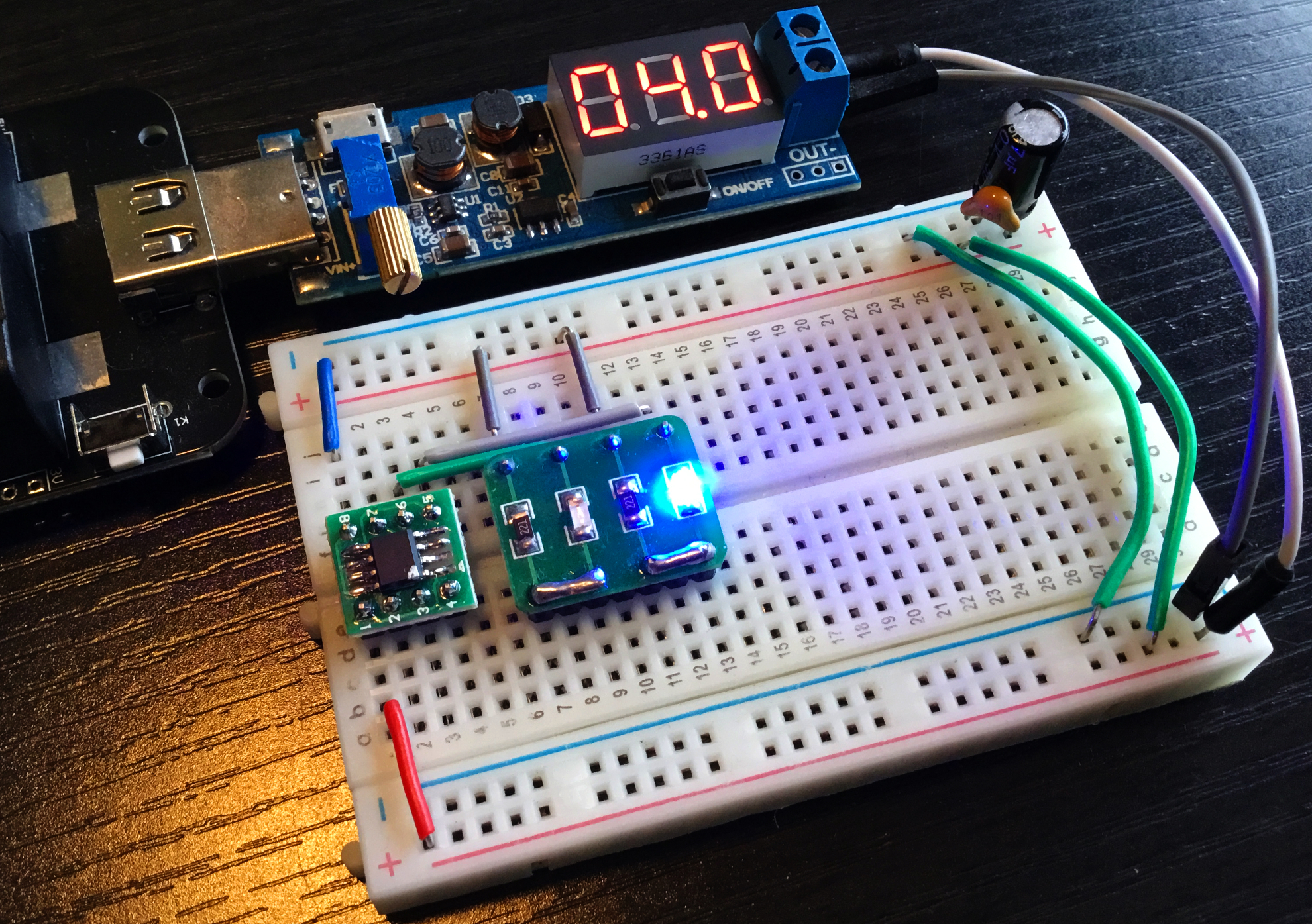
Nervously I transferred the programmed chip to a breadboard set up with the requisite connections and LEDs, turned on the power and was overjoyed to be greeted with blinking as required.
The next journey is to look at how this code works, then hopefully a repetition of the code in assembler. Looking ahead I would like to replace the ATTiny13 in the candle project with my own home grown Padauk assembler code. That should keep me a bit busy.
Thank you EEVBlog community, PCBWay and all those subscribers to the channel for your support, advice, encouragement and good will.
Which programmer is best this one or the one STM32 Mini-Pill https://oshwlab.com/socram8888/padauk-programmer
ReplyDelete