Squeezing down the power of a PFS154 until it gasps
There are days when I wish that I had never heard of the magnificent reverse engineering project on EEVBlog for the Padauk range of microcontrollers. It is a wonderful piece of work put together by a talented group of individuals, but it is also a very deep rabbit hole from which it is difficult to escape.
There are other days when I claw back some sanity with a little win over this processor. It is often after trawling through datasheets, blogs and forums and piecing together a few snippets of code or advice that I have these tiny victories.
I've always got my eyes on the prize of having solar "candles" driven in part by these "cheap" devices. I write "cheap" even though the cost of time and components for the programmers is surely ridiculous (and I cheerfully avoid any damning tallies).
Here are some of the requirements that have contributed to this goal:
| Feature | Blog | Video |
| Designing a circuit that collects solar energy and can deliver that power reliably to a microcontroller |
|
|
| Choosing an LED that is cheap, small, allows three channels and puts out a candle-like light | Blog Link | YT Link |
| Changing the energy requirements of a microcontroller for efficiency (lower frequency and voltage) | Blog Link | YT Link |
| Making a Programmer that can code up a Padauk chip | Blog Link | YT Link |
| Experiments in Random numbers to mimic a candle flame | Blog Link | YT Link |
| Working with PWM on the PFS154 | Blog Link | YT Link |
| 8-bit AVR code upgraded to 16-bit for the PWM output of the PFS154 | Blog Link | YT Link |
| Can I make a PFS154 work? (not strictly candle based, but part of exploring this chip) | Blog Link | YT Link |
One of the joys of the ATTiny13 based candle is the very low energy requirements. I was able to run the chip with minimal energy requirements by lowering the clock frequency (128Mhz) and the voltage (3V). Now we are at a similar point with the Padauk version.
So I was chuffed to see Tim on his blog talking up the low energy blinker he made from the PFS154 - complete with code!
/* ---------------------------------------------------
	Ultra Low Power LED flasher
	LED is connected to PA4 and is high active.
	Jan 16th, 2021,  CPLDCPU - Initial version
  ---------------------------------------------------- */

#include <stdint.h>
#include <pdk/device.h>
#include <pdk/delay.h>

unsigned char _sdcc_external_startup(void)
{
	PDK_SET_FUSE(FUSE_IO_DRV_LOW);	// Set output driving strength to low

	CLKMD =  CLKMD_ILRC | CLKMD_ENABLE_ILRC | CLKMD_ENABLE_IHRC;
	CLKMD =  CLKMD_ILRC | CLKMD_ENABLE_ILRC ;

		// Note: it is important to turn off IHRC only after clock settings
		// have been updated. Otherwise the CPU stalls.
	return 0; // perform normal initialization
}

void main(void)
{

	// Toggling PA4 at ILRC (53kHz): 86 µA
	// Toggling PA4 at ILRC_dev16 (53kHz): 66.7 µA
	// Stopsys with 5V: 0.5 µA
	// The watchdog cannot wake up from stopexe!!

	PADIER = 0; // disable pins as wakeup source
	PBDIER = 0; // Also port B needs to be disabled even if it is not connected
		    // to the outside of the package. touching the package can introduce
		    // glitches and wake up the device

	INTEN = 0;  // Make sure all interrupts are disabled
	INTRQ = 0;

	MISC = MISC_FAST_WAKEUP_ENABLE;  // Enable faster wakeup (45 clocks instead of 3000)
									 // This is important to not waste energy, as 40µA bias is already added during wakeup time

	// Configure timer two for output on PA3
	// --> Works, timer2 and 2 can be used for PWM while CPU is in STOPEXE mode
	// It appears that also timer 2 can wake up the CPU. This is not maskable?

	TM2C  = TM2C_CLK_ILRC | TM2C_MODE_PWM;  // Oscilator source for timer 2 is LRC (53 kHZ)
	TM2CT = 0;
	TM2S  = TM2S_PRESCALE_DIV16 | TM2S_SCALE_DIV8; // Divide clock by 16*7=112 -> 53 kHz / 122 = 414 Hz
	TM2B  = 1;  // PWM threshold set to 1. The PWM event will trigger the wakeup. Wakeup occurs with 414 Hz / 256 = 1.66 Hz

	PA		= 1<<4;  // LED is on PA4, set all other output to zero.
	PAPH 	= 0;	         // Disable all pull up resistors
	PAC		= 0;     // Disable all outputs
				 // Note: There is no series resistor for the LED
				 // The LED current is limited to 2-4 mA by LOW IO driving setting
				 // See Setction 4.14 (p24) in PFS154 manual

	for (;;) {
		PAC |=1<<4;  // Enable LED output (It's set to High)
		__nop();
		__nop();
		__nop();
		PAC &=~(1<<4); // Disable LED output after 4 cycles => 4/53 kHz = 75.5 µS
		__stopexe();
	}
}
I did make one small change in the end (not in the video) where I add a delay based on about 50 "nop" instructions so that the time "on" is greater (but also it uses more energy).
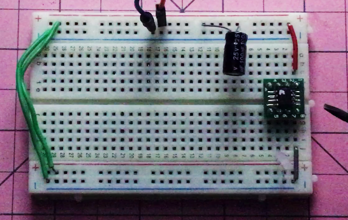
After wiring up the circuit and flashing the code...success! Low energy flashing LED from the PFS154.
No comments:
Post a Comment