Pimping the ESP32-CAM
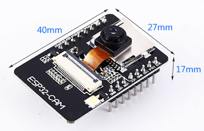
The ESP-32 CAM module is a pretty good (and usually cheap) bit of kit. I've used them about the place at times because they are quick and easy to setup.
Recently during a blog and video about a 3D print I mentioned en passant that I use an ESP32 which has been "pimped" to include control over the bright onboard LED. Plus I wanted better performance and some other features.
Note that I use Linux exclusively - I imagine that the process is pretty similar with Windows except for the multiple reboots required when Windows installs software!
In this blog and video I'm going to cover:
1. Programming the ESP-32 Cam module (connections/IDE/etc)
In the past I have programmed this module just using an Arduino and a few wires. The connections are simple and it works fine with the ESP32 CAM sitting on a breadboard.
The Arduino is programmed as "ArduinoISP", a sketch found in the examples menu of the Arduino IDE.
An alternative would be to use a programming module such as the following.
Unfortunately due to my filing system I am unable to find my version of this module, so in the meantime I decided to build my own with a generic Arduino shield PCB ordered years ago!
In the video I show a rudimentary version of this shield with the minimum VCC/GND connections, TX/RX and a button between GND and IO0 to put the ESP32 CAM into programming mode.
The ESP32-CAM board files for the Arduino IDE can be found here:
...or you can simply go to the Arduino preferences and copy and paste the following:
https://raw.githubusercontent.com/espressif/arduino-esp32/gh-pages/package_esp32_index.json
...as per this picture...
Then when you go to "tools", "boards" and "board manager" you can do a search for ESP32 and install the package as shown.
To test the rig I simply programmed up a couple of blinky sketches, in particular accessing the onboard LED (GPIO4) on the module - an important feature for lighting the scene.
NOTE: to program the board the button must be pressed to bring GPIO0 to GND and allow the ESP32 to be programmed, then after pressing the button again to release the connection and resetting the module, the blinking goodness shall begin!
void setup() {
  pinMode(4, OUTPUT);
}

void loop() {
  digitalWrite(4, HIGH);
  delay(100);
  digitalWrite(4, LOW);
  delay(2000);
}
2. Uploading and running the "standard" software
When you are ready to access the camera, select the ESP32 CAM board as shown:
Then select the camera web server example as shown:
After you have changed the WiFi SSID and Password in the code and uploaded, you will need "unpress" the programming button, reset the device and then find it on your local network (e.g. by checking with your router, or using a piece of software such as nmap).
Once you have found your device you simply start a browser on the network and then type the address into the address bar.
The standard interface is fine and runs OK, but I wanted to trim up the code a bit (I didn't really need facial recognition for 3D printing!) and mainly I wanted access to the onboard LED.
So I started looking for alternative camera web servers.
3. Sourcing and uploading alternative software
I tested a few different versions of the web server until I found the right one for me, which turned out to be the following:
When you download the github code you can unzip it into a folder. Navigating to the "binarys" folder you can then upload the binaries to your ESP32 camera using the following command (also found in that directory in the "flashing.txt" file), again making sure that the device is in programming mode by pressing the button and resetting.
esptool.py --chip esp32 --port "/dev/ttyUSB0" --baud 921600 --before "default_reset" --after "hard_reset" write_flash -z --flash_mode "dio" --flash_freq "80m" --flash_size detect 0x1000 bootloader.bin 0x10000 espcam.bin 0x8000 partitions.bin
Unlike the standard web server version, you will need to make serial contact with the device e.g. via putty, press the space bar within 2 seconds of resetting it, and then enter your WiFi credentials for storage on the ESP32.
But once you're there, the interface is worth it!
4. Compiling and installing alternative software
The final phase (if you think it necessary, and you're more than a bit nerdy) is to compile the binary files yourself. To do this, follow the steps below:
a) download the esp-idf from github, and follow the instructions to install the development softwareb) change directory to where the Makefile is for the ESP32-CAM softwarec) type "source /path-to-esp-idf/export.sh"d) "make" then upload binaries as before, ore) "make flash" to both make and upload binaries to your ESP32-CAM
That's it!


No comments:
Post a Comment