Saturday, November 28, 2020

0000 0000 0100 1011

Not really electronics (or is it?)

A quick tour of the 3D printing bench this week, mainly for me so that I don't forget all of the twists and turns in making the tracking software/hardware and the photographing software/hardware work as expected and required.

1. The printer

I had been thinking about a 3D printer for a couple of years, for a couple of reasons. Firstly, I hate jumping in the car and driving 30 minutes to the nearest hardware store to grab some stupid piece of plastic that costs $7 to buy, but probably one hundredth of that price to manufacture. A waste of time and money!

Secondly, there have been some projects which I have shoe-horned into off the shelf boxes, but then I have had to modify/extend etc., because some cable or other wasn't quite fitting in the enclosure.

Finally, I saw PileOfStuff and his Creality Ender 3 V2 and the die was cast. My limited research had also pointed me towards this model, and so after negotiations with the Minister of Finance I was able to purchase the unit locally and then wait by the postbox for it's arrival. While I waited (a week or so) I consumed all manner of YouTube videos about how to unpack, setup and test the printer, before settling on this explanation which worked fine. The whole process from box to first print took around 2 hours which I thought was pretty reasonable.

One extra useful step was to download and have handy some gcode that assists with leveling the print bed. I did it manually a couple of times (thanks YouTube), but the code makes it so much easier, and semi-automatic.

The Minister of Finance demanded that the first print be all about plastic pigs, and so this was the test run result while I fiddled with all the settings in the learning process (and in the end only one pig trotter fell off - to be superglued back on with nobody the wiser).


A week or so and after a few prints I came to realise that the bed was having trouble maintaining consistent temperature in the basement workshop, mainly because it could be as low as 3 degrees Celsius down there even at this time of year, with the odd breeze when doors are opened.

Also the space is a bit dusty which is not great for electronics or servo motors. I had been covering up the printer with a big plastic rubbish bag when not in use, but in the end I placed an additional online order for a medium Creality enclosure, and although it turned out to be comically large it was of course suitable for the task.


2. The OctoPrint solution.

On cold nights after work I was becoming more reluctant to trudge down and check the printer, so I downloaded Armbian for an Orange Pi Zero that I had lurking about in a cupboard. 

Quite a few online gurus were adamant that this was a bad combination, and that I would need to buy a late model Raspberry Pi to have any success. But after following an excellent online tutorial I had the thing up and running and reporting back the progress (or otherwise) of the print.

Occasionally a print was "lost" and the printer would grind to a halt awaiting further instructions. It turns out that the mountain of concrete between the upstairs router and the puny antenna of the Orange Pi Zero could be the weakest link.

In response to this issue I pressed into service a cheapo WiFi extender laying about doing very little, and all has been fine since.


The first thing I printed from this new setup was a nice box for the Orange Pi Zero, and I slapped a fan on the top with 5V power provided by the main board. It works a treat in keeping the board cool and calm.


I was also motivated to 3D print a side holder for the filament for a couple of reasons. Firstly, the filament wasn't flowing real well and it sometimes became "semi-stuck" with the wacky angle of attack from the top of the printer.

Secondly, I eventually would like to put the printer up on a concrete block with vibration dampers as seen in this video - and so to fit in the "medium" enclosure the spool must migrate to the side, providing the needed vertical space.

The side spool holder print went well and the result is lovely (and works a treat!). I did add a homemade spring to help align the spool with the feeder.


3. Getting a picture

I started to think about how I could get an actual picture of the print so that I could monitor the printer from the warmth and comfort of an armchair upstairs. Experts online assured me that the Orange Pi Zero would struggle, although I still like the idea of using an old laptop camera wired in for the job.

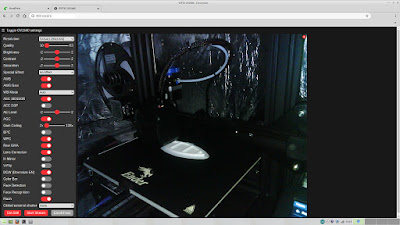
However, I did also have an ESP-32 Cam module acquired for a song which maybe could be pressed into service. The example camera webserver code provided with the ESP-32 board definitions was simple and worked well, but I could not see the ongoing printing in the low light of the enclosure, and as well it seemed silly that the camera module (and printed box) had a bright LED but that it didn't seemed to be accessible on the standard web server page.

After a quick play with a bluetooth option (it slowed down picture acquisition too much for me) along comes the genius of Hermann Stamm-Wilbrandt and his modified webserver...and we now have a "flash" button to play with in order to light up the scene and take great pics or streams of the printing action. Nice one, Hermann!

I then printed a 3D printed box to wrap the ESP32 in (with two warnings: the lid needs to be separated out from the other components - I used "MeshLab" and then it needed to be flipped in Ultimaker Cura for access to the 5V/GND pins; also make sure that you do at least a 40% infill for added strength needed for the "ball" part of the construction) and all went well. You can see mine printed below with a modified white lid indicating the flipped access point.


#include "esp_camera.h"
#include <WiFi.h> // // WARNING!!! Make sure that you have either selected ESP32 Wrover Module, // or another board which has PSRAM enabled // // Select camera model //#define CAMERA_MODEL_WROVER_KIT //#define CAMERA_MODEL_ESP_EYE //#define CAMERA_MODEL_M5STACK_PSRAM //#define CAMERA_MODEL_M5STACK_WIDE #define CAMERA_MODEL_AI_THINKER #include "camera_pins.h" const char* ssid = "*********"; const char* password = "*********"; const int pin_vsync = VSYNC_GPIO_NUM; void startCameraServer(); void setup() { Serial.begin(115200); Serial.setDebugOutput(true); Serial.println(); camera_config_t config; config.ledc_channel = LEDC_CHANNEL_0; config.ledc_timer = LEDC_TIMER_0; config.pin_d0 = Y2_GPIO_NUM; config.pin_d1 = Y3_GPIO_NUM; config.pin_d2 = Y4_GPIO_NUM; config.pin_d3 = Y5_GPIO_NUM; config.pin_d4 = Y6_GPIO_NUM; config.pin_d5 = Y7_GPIO_NUM; config.pin_d6 = Y8_GPIO_NUM; config.pin_d7 = Y9_GPIO_NUM; config.pin_xclk = XCLK_GPIO_NUM; config.pin_pclk = PCLK_GPIO_NUM; config.pin_vsync = VSYNC_GPIO_NUM; config.pin_href = HREF_GPIO_NUM; config.pin_sscb_sda = SIOD_GPIO_NUM; config.pin_sscb_scl = SIOC_GPIO_NUM; config.pin_pwdn = PWDN_GPIO_NUM; config.pin_reset = RESET_GPIO_NUM; config.xclk_freq_hz = 20000000; config.pixel_format = PIXFORMAT_JPEG; //init with high specs to pre-allocate larger buffers if(psramFound()){ config.frame_size = FRAMESIZE_UXGA; config.jpeg_quality = 10; config.fb_count = 2; } else { config.frame_size = FRAMESIZE_SVGA; config.jpeg_quality = 12; config.fb_count = 1; } #if defined(CAMERA_MODEL_ESP_EYE) pinMode(13, INPUT_PULLUP); pinMode(14, INPUT_PULLUP); #endif // camera init esp_err_t err = esp_camera_init(&config); if (err != ESP_OK) { Serial.printf("Camera init failed with error 0x%x", err); return; } sensor_t * s = esp_camera_sensor_get(); //initial sensors are flipped vertically and colors are a bit saturated if (s->id.PID == OV3660_PID) { s->set_vflip(s, 1);//flip it back s->set_brightness(s, 1);//up the blightness just a bit s->set_saturation(s, -2);//lower the saturation } //drop down frame size for higher initial frame rate s->set_framesize(s, FRAMESIZE_QVGA); #if defined(CAMERA_MODEL_M5STACK_WIDE) s->set_vflip(s, 1); s->set_hmirror(s, 1); #endif WiFi.begin(ssid, password); while (WiFi.status() != WL_CONNECTED) { delay(500); Serial.print("."); } Serial.println(""); Serial.println("WiFi connected"); startCameraServer(); Serial.print("Camera Ready! Use 'http://"); Serial.print(WiFi.localIP()); Serial.println("' to connect"); } void loop() { // put your main code here, to run repeatedly: delay(10000); }


No doubt there are many more mods for this printer to come (e.g. a filament guide) but at this point and after a couple of weeks I have to say that it's a very good printer for the price, and the super cheap additions of an Orange Pi Zero and ESP-32 CAM just make the whole printing process so much easier to set up and monitor.


Saturday, November 21, 2020

0000 0000 0100 1010

PCF8563 Time/Date IC

Slightly obsessed with timing devices (really?!), I saw these PCF8563 real time clock chips that had so many features and looked too good to be true (and so cheap!). I grabbed some that were already made up in modules, and others that are just raw IC chips ready to be used in an appropriate circuit.

In this blog I am going to focus on the raw IC version and try to get it going so that I can measure and store time.

The first order of business is to solder up the SOP8 package onto a DIP8 adapter. I put some extra white paint on the little fella so that I know it's not an AVR or PADAUK when I reach for it!


The plan is to put this on a breadboard and then:

  1. program an Arduino Nano to push out the time/date to the RTC
  2. everything sleeps in low current mode
  3. pushing a button wakes up the Nano
  4. the Nano polls the RTC for time and date (and turns on an LED for good measure, also who doesn't like a blinking LED?)
  5. the Nano pushes out the time/date to an OLED display for a few seconds
  6. everyone goes back to sleep
  7. battery backup the whole shebang with a coin cell battery?
  8. swap out the Nano for an ATMega328 to further reduce the current requirements?

I am more than a little unhappy with the internet over this little circuit, for a couple of reasons. Firstly when I looked for a likely setup, I came across this site with the following picture.


Even though from previous experience with crystals I knew that capacitors need to be used to get the things oscillating, the only capacitor mentioned on the page is for decoupling and it's not near the crystal.

Upshot? I spent a "happy" couple of hours trying to debug code that clearly showed the Nano talking to the RTC, and vice versa, but the RTC not "ticking" in any clock-like manner. This problem was eventually solved with the addition of a 20pf capacitor between the crystal and ground. Do I need to put one on the other side? I'm not sure! At this point I was just happy to see the little fella measuring the <frustrating long> passage of time.


Secondly there were a LOT of libraries purporting to help communicate with the PCF8563. Sadly many had holes and it took quite a bit of fiddling to realise that this library is the easiest and most functional. It's found and installed very quickly using the Arduino IDE "Library Manager" dialog.

I also realised that for my sanity to prevail I would work with two lots of (very similar) code, one to set the RTC and one to then read it on demand. I have seen these combined on some sites with similar software via a "flag" or test, but it seemed just as easy to separate out these similar but fundamentally different functions, even though much of the rest of the code is the same.

I've highlighted the essential difference.

Setting Code:

/*
   Using an PCF8563 as an RTC for an Arduino Nano
   and an OLED display

   One Circuit Friday 13 November 22:26:09 AEDT 2020
   Friday 13th! Yikes!
*/

#include <Wire.h>
#include "RTClib.h"
#include <avr/sleep.h>
#include <Adafruit_GFX.h>
#include <Adafruit_SSD1306.h>

// some variables and constants
byte thehour = 0;
byte theminute = 0;
byte thesecond = 0;
byte theday = 0;
byte themonth = 0;
int theyear = 0;
String myminute = "minute";
String mysecond = "second";
const byte ledPin = 4;
const byte interruptPin = 2;
volatile boolean button = false;

#define OLED_RESET -1
#define SCREEN_WIDTH 128
#define SCREEN_HEIGHT 32

// initialise our I2C devices
RTC_PCF8563 rtc;
Adafruit_SSD1306 display(SCREEN_WIDTH, SCREEN_HEIGHT, &Wire, OLED_RESET);

// button ISR
void wakeUpNow() {
  button = true;
}

// sleep routine
void sleepNow() {
  set_sleep_mode(SLEEP_MODE_PWR_DOWN);  
  sleep_enable();         
  sleep_mode(); 
  sleep_disable(); 
  detachInterrupt(0);
}

void setup () {
  while (! rtc.begin()) {
    delay(500);
  }
  delay(1000); // settle rtc
  pinMode(ledPin, OUTPUT);
  pinMode(interruptPin, INPUT_PULLUP);
  attachInterrupt(digitalPinToInterrupt(interruptPin), wakeUpNow, RISING);
  rtc.adjust(DateTime(F(__DATE__), F(__TIME__)));

  if (!display.begin(SSD1306_SWITCHCAPVCC, 0x3C)) { // Address 0x3C for 128x64
    for (;;);
  }
  display.clearDisplay();
  display.setTextSize(1);
  display.setTextColor(SSD1306_WHITE);
  display.setCursor(10, 0);
  display.println("OneCircuit Clock");
  display.display();
  delay(3000);
  display.clearDisplay();
  display.display();
}

void showtime() {
  digitalWrite(ledPin, HIGH);
  DateTime now = rtc.now();
  thehour = now.hour();
  theminute = now.minute();
  // make it pretty if the numbers are below 10
  if (theminute < 10) {
    myminute = "0" + String(theminute);
  }
  else {
    myminute = String(theminute);
  }
  thesecond = now.second();
  if (thesecond < 10) {
    mysecond = "0" + String(thesecond);
  }
  else {
    mysecond = String(thesecond);
  }
  theday = now.day();
  themonth = now.month();
  theyear = now.year();
  // string together the date/time (pun intended)
  String nowtime = "TIME " + String(thehour) + ":" + myminute + ":" + mysecond;
  String nowdate = "DATE " + String(theday) + "/" + String(themonth) + "/" + String(theyear);
  display.setCursor(10, 0);
  display.println("OneCircuit Clock");
  display.setCursor(10, 15);
  display.println(nowtime);
  display.setCursor(10, 25);
  display.println(nowdate);
  display.display();
  delay(5000);
  digitalWrite(ledPin, LOW);
  display.clearDisplay();
  display.display();
  button = false;
  attachInterrupt(digitalPinToInterrupt(interruptPin), wakeUpNow, RISING);
}

void loop() {
  if (button) {
    showtime();
  }
  sleepNow();
}

Reading Code:

/*
   Using an PCF8563 as an RTC for an Arduino Nano
   and an OLED display

   One Circuit Friday 13 November 22:26:09 AEDT 2020
   Uh Oh - Friday 13th...
*/

#include "RTClib.h"
#include <avr/sleep.h>
#include <Adafruit_GFX.h>
#include <Adafruit_SSD1306.h>

// some variables and constants
byte thehour = 0;
byte theminute = 0;
byte thesecond = 0;
byte theday = 0;
byte themonth = 0;
int theyear = 0;
String myminute = "minute";
String mysecond = "second";
const byte ledPin = 4;
const byte interruptPin = 2;
volatile boolean button = false;
#define OLED_RESET -1
#define SCREEN_WIDTH 128
#define SCREEN_HEIGHT 32

// initialise our I2C devices
RTC_PCF8563 rtc;
Adafruit_SSD1306 display(SCREEN_WIDTH, SCREEN_HEIGHT, &Wire, OLED_RESET);

// button ISR
void wakeUpNow() {
  button = true;
}

// sleep routine
void sleepNow() {
  set_sleep_mode(SLEEP_MODE_PWR_DOWN);
  sleep_enable();
  sleep_mode();
  sleep_disable();
  detachInterrupt(0);
}

void setup () {
  pinMode(ledPin, OUTPUT);
  pinMode(interruptPin, INPUT_PULLUP);
  while (! rtc.begin()) {
    delay(500);
  }
  delay(1000); // settle rtc
  attachInterrupt(digitalPinToInterrupt(interruptPin), wakeUpNow, RISING);
  DateTime now = rtc.now();
  if (!display.begin(SSD1306_SWITCHCAPVCC, 0x3C)) { // Address 0x3D for 128x64
    for (;;);
  }
  display.clearDisplay();
  display.setTextSize(1);
  display.setTextColor(SSD1306_WHITE);
  display.setCursor(10, 0);
  display.println("OneCircuit Clock");
  display.display();
  delay(3000);
  display.clearDisplay();
  display.display();
}

void showtime() {

  digitalWrite(ledPin, HIGH);
  DateTime now = rtc.now();
  thehour = now.hour();
  theminute = now.minute();
  // make it pretty if the numbers are below 10
  if (theminute < 10) {
    myminute = "0" + String(theminute);
  }
  else {
    myminute = String(theminute);
  }
  thesecond = now.second();
  if (thesecond < 10) {
    mysecond = "0" + String(thesecond);
  }
  else {
    mysecond = String(thesecond);
  }
  theday = now.day();
  themonth = now.month();
  theyear = now.year();
  // string together the date/time (pun intended)
  String nowtime = "TIME " + String(thehour) + ":" + myminute + ":" + mysecond;
  String nowdate = "DATE " + String(theday) + "/" + String(themonth) + "/" + String(theyear);
  display.setCursor(10, 0);
  display.println("OneCircuit Clock");
  display.setCursor(10, 15);
  display.println(nowtime);
  display.setCursor(10, 25);
  display.println(nowdate);
  display.display();
  delay(5000);
  digitalWrite(ledPin, LOW);
  display.clearDisplay();
  display.display();
  button = false;
  attachInterrupt(digitalPinToInterrupt(interruptPin), wakeUpNow, RISING);
}

void loop() {
  if (button) {
    showtime();
  }
  sleepNow();
}

After all of this fiddling about I was able to breadboard the devices together and make the clock a reality.


The battery backup proved useful for kicking out the programming USB cable as the power supply and running the device independently via a battery bank, with a coin cell battery stuck in to keep the clock ticking.

For backup power to work properly I needed to put in a diode (1N4148 in my case) from the 5V to the IC and another one from the battery (3.3V) to the IC. I'm pretty sure a Schottky would be fine as well for this job. The diodes prevent the backup from trying to run the whole circuit when the power is out, and also to prevent the 5V from the main battery/power source from interfering with the coin cell.

Just for "fun" and as seen in the picture above, I also compiled the code for the ATMega328 which worked fine - nice one!


Saturday, November 14, 2020

0000 0000 0100 1001

MT3608 voltage regulator

A happy coincidence was the arrival of a heap of MT3608 chips in different circumstances. Firstly I had re-ordered the ubiquitous voltage regulator modules, not realising at the time that the ICs at their heart also form a part of the "Pesky Padauk Programmer Project"™ (parts one, two and three).

And so a bunch of raw chips showed up as well, some of them acquired just to see if and how to I could make a DC-DC boost converter. I have blown up a few of these ready-made modules in my time, and I'm not the only one!

My goal for this IC was to first make a successful 15V boost converter from a low voltage source, and then to see if I could maybe vary the output voltage by using a pot connected to the IC itself, and then maybe by using a PWM signal (?) feeding into the IC. 

From the datasheet comes:


The freepdk programmer uses 240k as R1 and 10k as R2 and so the voltage should be 0.6x(1+240/10)=15V. 


The tiny little fella looks great shackled onto an adapter built for an entirely different chip!


The FreePDK Padauk Programmer also uses some other components to maybe output different voltages programmatically via PWM?


The BSS84 is a PNP Mosfet (-0.13 A, -50 V) and the BSS138 (0.22 A, 50 V) is an NPN Mosfet and in this configuration with control coming from the STM32 I can only assume it turns on and off the 15V, but I was curious to see if it could also limit or control the voltage through some sort of PWM. 

The circuit diagram indicates some sort of Frankenstein Mosfet Sziklai pair, but I wasn't able to find any definitive information on this type of circuit, and my own experiments remain inconclusive, at this stage.


Saturday, November 7, 2020

0000 0000 0100 1000

"Blinky" the Ice Blue Solar Light

Putting the Stable Joule Thief (SJT) into service, in this post I am cutting the guts out of a standard solar garden light and making an ice blue blinking version. I'm not sure why.

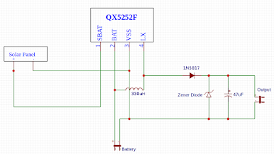
Firstly the SJT itself which is a variation on the QX5252 IC circuit which looks like:


Using this circuit I've made up a few PCBs that allow a slow running ATTiny13a (at 128kHz) to be programmed. This one sleeps incessantly and just wakes up and blinks an LED from time to time (0.125s on, 2s off).

Here's the PCB version I'm using for this project.


Needing some code to sleep and blink the microcontroller, I dug out an old assembly project and modified it as follows:

.nolist
.include "tn13adef.inc" ; Define device ATtiny13A
.list
; **********************************
;        H A R D W A R E
; **********************************

; Device: ATtiny13A, Package: 8 - pin - PDIP_SOIC
;
;           ____________
;        1 /            | 8
;      o-- | RESET  VCC | --o
;      o-- | PB3    PB2 | --o
;      o-- | PB4    PB1 | --o
;      o-- | GND    PB0 | --o
;        4 |____________| 5
;

; **********************************
;         C O D E
; **********************************

    .cseg
    .org 000000

; **********************************
; R E S E T  &  I N T - V E C T O R S
; **********************************
    rjmp Main               ; Reset vector
    reti ; INT0
    reti ; PCI0
    reti ; OVF0
    reti ; ERDY
    reti ; ACI
    reti ; OC0A
    reti ; OC0B
    rjmp mytimer_ISR        ; my interrupt
    reti ; ADCC

; **********************************
;  I N T - S E R V I C E   R O U T .
; **********************************

mytimer_ISR:

    ;  sleep is interrupted, program returns
    reti

; **********************************
;  M A I N   P R O G R A M   I N I T
; **********************************
;
Main:
    ldi r16, Low(RAMEND)
    out SPL, r16              ; Init LSB stack pointer

    ; output mode for PB4, input for the rest
    ldi r16, 0b00010000
    out DDRB, r16

    ; turn on PB4, enable internal pullups
    ; on the rest of the pins
    ldi r16, 0b11111111
    out PORTB, r16

; **********************************
;    P R O G R A M   L O O P
; **********************************

Loop:

    rcall waitabit            ; 1/8 second (on)
    rcall waitalot            ; 2 seconds (off)

    rjmp loop

waitabit:

    ; reset watchdog timer
    wdr

    ; 1/8 second timer
    ldi r16, 0b01000011       ; see datasheet
    out WDTCR, r16

    rcall sleepnow
    rcall flipbit
    ret

waitalot:

    ; reset watchdog timer
    wdr

    ; 2 second timer
    ldi r16, 0b01000111      ; see datasheet
    out WDTCR, r16

    rcall sleepnow

    ; finished long sleep, so flip LED
    rcall flipbit

    ret


sleepnow:

    ; see datasheet MCUCR, ADCSRA, BODCR

    ; sleep enable, power down mode
    ldi r16, 0b00110000
    out MCUCR, r16

    ; disable ADC
    ldi r16, 0b00010000
    out ADCSRA, r16

    ; disable interrupts to make sure the following
    ; timed sequence is not interrupted
    cli

    ; disable BOD - must be done in a timed sequence
    ; as follows, write 1 to BODS and BODSE then within
    ; four clock cycles write 1 to BODS and 0 to BODSE
    ; then within three clock cycles enable sleep
    ; page 33 on the datasheet

    ldi r16, 0b00000011
    ldi r17, 0b00000010
    out BODCR, r16
    out BODCR, r17

    sei

    sleep

    ; sleep disable
    ldi r16, 0b00000000
    out MCUCR, r16

    ret

flipbit:
    ; if PB4 is on, switch off and vice versa

    in r16, portb
    ldi r17, 0b00010000
    eor r16, r17
    out portb, r16

ret

; End of source code

I burned the fuses, compiled the code and uploaded the hex file to the ATTiny13a (see video below). After testing, I was ready to assemble the PCB back into the gutted solar light and flick it out to the garden - nice!

Now we wait for alien overlords to see the signal and come on down for a nice cup of tea and to say hello.