OLED clock via ATTiny85 and External 1MHz Timer
A couple of blogs ago I was fiddling with a 1MHz active crystal oscillator. After establishing that it wasn't full of tiny socks (long story), and also that it seemed pretty accurate, I hooked up the timer to an ATTiny85 to...er...blink an RGB LED.I did say in that blog that I would endeavour to use this external timing source to maybe make some sort of clock. The exact words were "I think that I will test this signal with a display to give the time of day, and check it periodically to see if it drifts over days/weeks."
The first decision then is how do I output the time? I have already done this with other processors using a TM1637 7-segment display module (works great), plus some other 7-segment options, but I have never played in the sandpit with an OLED display.
They look pretty cool and all of my reading seems to point to the fact that they are easy-ish to get up and running. I did have some blue 128x32 OLEDs in the bucket, so I ripped one out and onto the breadboard it went.
Now for some libraries. As I am using an ATTiny85, I'll either need to spend a few weeks nutting over the datasheet and learning way too much about I2C, time keeping and oled-ing, or borrow someone else's brain via libraries written for this little microcontroller. I chose the latter! There are a few good libraries around, but in the end I settled on the following:
#include <TinyI2CMaster.h>  // https://github.com/technoblogy/tiny-i2c
#include <Tiny4kOLED.h>     // https://github.com/datacute/Tiny4kOLED
#include <TimeLib.h>        // https://github.com/PaulStoffregen/Time
The next step was to write a heap of code with the following flow...
- Display the time
- Listen for button
- If button pushed, set the time
- Display the time
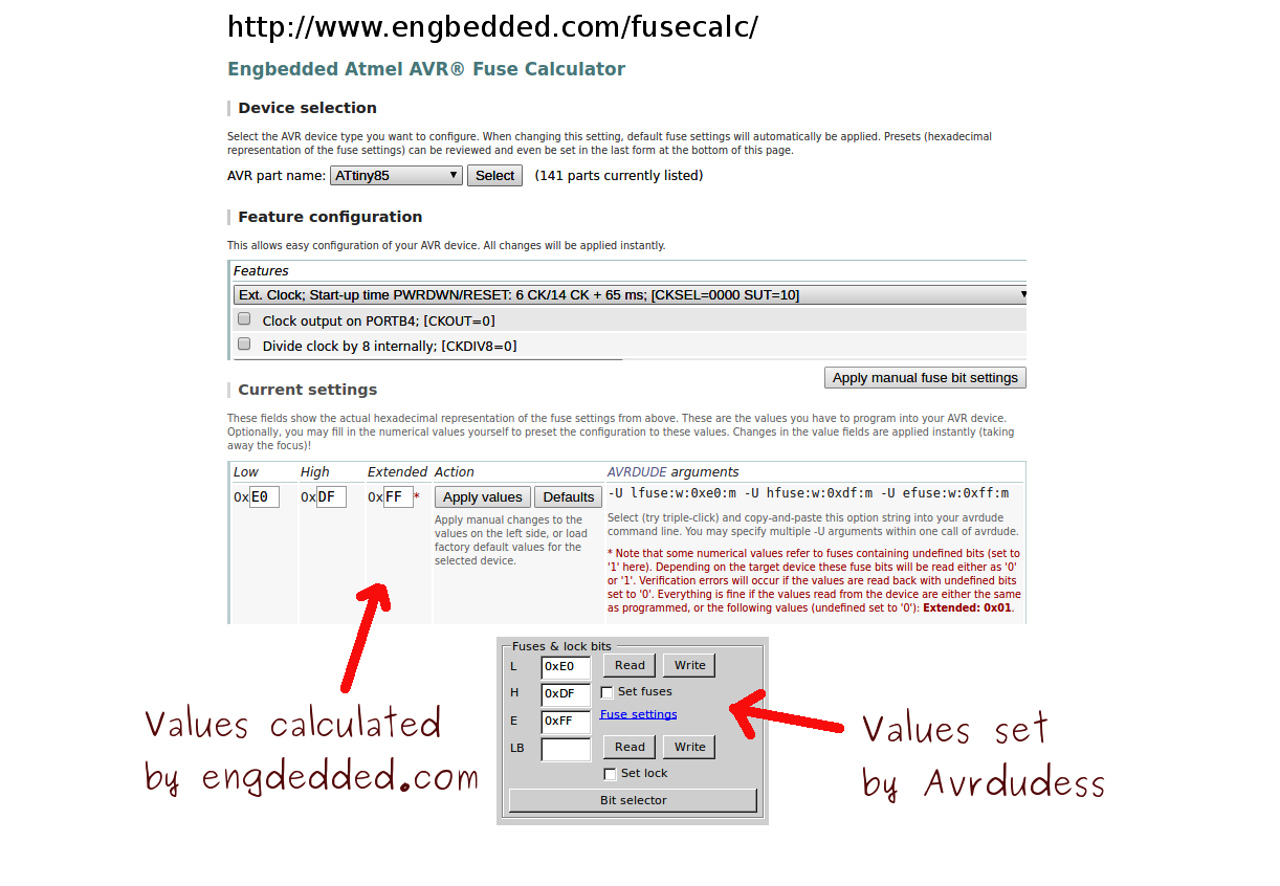
Days of rumination followed and in the end I dove deep into the ATTiny85 datasheet (OK, it was only page 26) where it is stated that for a single external clock source "the CKSEL Fuses must be programmed to 00”.
If I was reading it correctly then this would change the fuse settings from what I did last time (external crystal oscillator requiring both XTAL1/pin2 and XTAL2/pin3) to an external clock source only requiring one pin (CLK1/pin2). Heading over to the amazing AVR Fuse setting calculator site I saw that you could indeed set the fuses for an external clock signal, not just external crystal oscillator.

Here is the full code, and here is the programmer/clock on the breadboard.


Hello,
ReplyDeleteNice to meet you here.
This is elaine from PCBWay, and noticed your channel through your comment on our partner(
Gadget Reboot). Glad to know that you are an electronics maker. If you have any PCBs needs for your video use, pls feel free to let me know. Our pleasure to sponsor that for you. You can contact me: elaine@pcbway.com