Your own PCB (part II)
From time to time I'd like access to a variable square wave generator. For instance when (if?) some non-fake CD4026 chips turn up, they will need a clock signal. I have made a few hobby type circuits based on the 555 timer before and as it's such a familiar and venerable concept that I'd thought it would make the perfect circuit to convert to a bona fide manufactured PCB to show the ease of the process (once you know what you are doing!).
Firstly I cast around for a suitable variant. I really like the look of the circuit on a youtube video called "NE555 Signal Generator Tutorial PCB - 10 Hz to 10 KHz" from user "Electronics Projects - Stefano91ste". The video description generously includes links to the "gerber files" needed to make the PCB. I nearly pressed the button for JLCPCB to make them, but then thought that a smaller smd version might be more suitable for me - plus I can "panelize" the process and have quite a few made, maybe for some of my students.
 |
| The large through hole original version |
I started right from scratch and looked at a few resources describing how the timer produces the signal. Using this very cool website I played around a bit with the numbers to convince myself I could make a generator that produces a square signal from about 0.2Hz (2.5 seconds on, 2.5 seconds off) to about 1.5KHz. In fact by swapping out the resistors and capacitors R1, R2 and C the possibilities expand considerably. Let's check out a few by first calculating and then building circuits based on the diagram in the video.
 |
| The variable pot and switchable capacitors give flexibility |
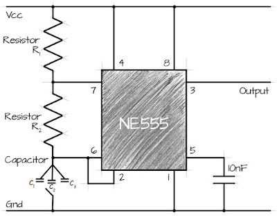
So I'll use the circuit shown below, where different values of the capacitance C in an SMD format are switched in and out along with variation of R2 using a 500kΩ potentiometer:
The next step is to make a prototype and test the calculated output of the circuit.
| C1 (nF) |
R1 (Ω) |
R2 fixed (Ω) |
R2 variable (Ω) |
R2 total |
Calculated f (Hz) |
Measured f (Hz) |
| 100.3 |
9959 |
9967 |
470000 |
479967 |
14.8 |
14.4 |
| 100.3 |
9959 |
9967 |
0 |
9967 |
480.3 |
477.0 |
| 9.685 |
9959 |
9967 |
470000 |
479967 |
153.3 |
149.0 |
| 9.685 |
9959 |
9967 |
0 |
9967 |
4973.9 |
5025.0 |
| 1.038 |
9959 |
9967 |
470000 |
479967 |
1430.3 |
1385.0 |
| 1.038 |
9959 |
9967 |
0 |
9967 |
46408.3 |
43950.0 |
The output frequency expected was calculated in a spreadsheet using the following formula:
So with the values soldered into the rig shown below I have been able to vary the signal output from about 15Hz to nearly 5kHz. I can go higher or lower if needed by changing the values of R1, R2 and C.
 |
| The test rig on a SMD to DIP adapter |
 |
| Measuring the output signal using a DSO138 |
In general the circuit works great - each capacitor/resistor combination is slightly "out" from calculated values, but of course the resultant signal can be adjusted using the potentiometer shown. I think the slight errors shown result from a combination of the cheap oscilloscope and the fact that all of these components including wires and breadboard have their own capacitance and impedance.
I'm happy that the proof of concept is now complete - next I will design the PCB online and then move closer to fabrication.


No comments:
Post a Comment