Friday, November 25, 2022

0000 0000 1011 0001

A Padauk PFS154 based "candle"

I have made a few variations of the ATTiny13 based "candle", including dedicated PCBs and assembler code driving two PWM channels to produce a candley flicker.

Lately I have branched out to a dedicated Padauk PFS154 PCB with a combined Stable Joule Thief circuit.

There are so many projects, videos, blogs etc over the years that I have made a little map to help me track what is going on!

I'm expecting a delivery from PCBWay for a small dedicated board (in orange on the diagram) for the LEDs of the project (more on this later), but the current work (in yellow on the diagram) is in the power delivery for the project and also with a PFS154 based PCB. 

The green node on the diagram is pie in the sky ASM code for the Padauk chip. It is my strong desire to get into this aspect of the project, as I really enjoyed the assembly version of the ATTiny13 candle.

The current code is in "C" and looks like this:

/*
  Candle with Three PWM

  Pseudo-random flickering to simulate a candle. Output is
  via 3xPWM channels, variables can be changed to 
  alter the simulation

*/

#include <stdint.h>
#include <stdlib.h>
#include "../device.h"
#include "../easy-pdk/calibrate.h"
#include "../auto_sysclock.h"
#include "../delay.h"
#include <stdbool.h>

#define LED4_BIT 4
#define LED0_BIT 0
#define LED3_BIT 3

uint16_t myrand = 2901;  // happy birthday

// global variables randomised later for flickering, using the
// "waveslow" and "wavefast" arrays
uint8_t slowcounter = 0;
uint8_t medcounter = 0;
uint8_t fastcounter = 0;
uint8_t slowstart = 0;
uint8_t slowend = 0;
uint8_t medstart = 0;
uint8_t medend = 0;
uint8_t faststart = 0;
uint8_t fastend = 0;
uint8_t faster = 0;

uint8_t waveslow[] = {20, 30, 70, 100};
uint8_t wavemed[] = {25, 40, 100, 120};
uint8_t wavefast[] = {20, 30, 120, 140};

// booleans to keep track of "fading up" or "fading down"
// in each of the slow and fast cycles
bool fastup = true;
bool slowup = true;
bool medup = true;

void mydelay(uint8_t counter) {

  for (uint8_t thiscount = 0; thiscount <= counter; thiscount++) {
    _delay_us(1);
  }
}

uint16_t gimmerand(uint16_t small, uint16_t big) {
  myrand ^= (myrand << 13);
  myrand ^= (myrand >> 9);
  myrand ^= (myrand << 7);
  if (abs(myrand) % 13 == 0) {
  myrand = myrand - 23;
  }
  if (abs(myrand) % 17 == 0) {
  myrand = myrand + 11;
  }
  return abs(myrand) % 23 * (big - small) / 23 + small;
}

void getnewslow() {
  slowstart = gimmerand(waveslow[0], waveslow[1]);
  slowend = gimmerand(waveslow[2], waveslow[3]);
}

void getnewmed() {
  medstart = gimmerand(wavemed[0], wavemed[1]);
  medend = gimmerand(wavemed[2], wavemed[3]);
}

// initialise a new fast cycle including the new speed of cycle
void getnewfast() {
  faststart = gimmerand(wavefast[0], wavefast[1]);
  fastend = gimmerand(wavefast[2], wavefast[3]);
  faster = gimmerand(1, 3);
}

// Main program
void main() {

  // Initialize hardware
  // Set LED as output (all pins are input by default)
  PAC |= (1 << LED4_BIT) | (1 << LED0_BIT) | (1 << LED3_BIT);

  // see datasheet
  PWMG1DTL = 0x00; 
  PWMG1DTH = 0x00;
  PWMG1CUBL = 0xff; 
  PWMG1CUBH = 0xff;
  PWMG1C = 0b10100111;
  PWMG1S = 0b00000000;

  PWMG0DTL = 0x00;   
  PWMG0DTH = 0x00;
  PWMG0CUBL = 0xff;
  PWMG0CUBH = 0xff;
  PWMG0C = 0b10100111;
  PWMG0S = 0b00000000;

  PWMG2DTL = 0x00; 
  PWMG2DTH = 0x00;
  PWMG2CUBL = 0xff;
  PWMG2CUBH = 0xff;
  PWMG2C = 0b10100111;
  PWMG2S = 0b00000000;

  getnewfast();
  getnewslow();
  getnewmed();
  slowcounter = slowstart;
  fastcounter = faststart;
  medcounter = medstart;

  // Main processing loop
  while (1) {

    // ramp up slow
    if (slowup) {
      slowcounter++;
      if (slowcounter > slowend) { // ramp finished so switch boolean
        slowup = !slowup;
      }
    }
    else {
      // ramp down slow
      slowcounter--;
      if (slowcounter < slowstart) { // ramp finished so switch boolean
        slowup = !slowup;
        getnewslow();
      }
    }

    // ramp up med
    if (medup) {
      medcounter++;
      if (medcounter > medend) { // ramp finished so switch boolean
        medup = !medup;
      }
    }
    else {
      // ramp down med
      medcounter--;
      if (medcounter < medstart) { // ramp finished so switch boolean
        medup = !medup;
        getnewmed();
      }
    }

    // ramp up fast
    if (fastup) {
      fastcounter = fastcounter + faster;
      if (fastcounter > fastend) { // ramp finished so switch boolean
        fastup = !fastup;
      }
    }
    else {
      // ramp down fast
      fastcounter = fastcounter - faster;
      if (fastcounter < faststart) { // ramp finished so switch boolean
        fastup = !fastup;
        getnewfast();
      }
    }
    // delay + a re-purposed random for ramp speeds
    mydelay(3 + faster);

    PWMG1DTL = slowcounter & 255;
    PWMG1DTH = slowcounter;
    PWMG0DTL = fastcounter & 255;
    PWMG0DTH = fastcounter;
    PWMG2DTL = medcounter & 255;
    PWMG2DTH = medcounter;

  }
}

// Startup code - Setup/calibrate system clock
unsigned char _sdcc_external_startup(void) {

  // Initialize the system clock (CLKMD register) with the IHRC, ILRC, or EOSC clock source and correct divider.
  // The AUTO_INIT_SYSCLOCK() macro uses F_CPU (defined in the Makefile) to choose the IHRC or ILRC clock source and divider.
  // Alternatively, replace this with the more specific PDK_SET_SYSCLOCK(...) macro from pdk/sysclock.h
  
   // AUTO_INIT_SYSCLOCK();

    PDK_SET_SYSCLOCK(SYSCLOCK_ILRC_DIV4);

  // Insert placeholder code to tell EasyPdkProg to calibrate the IHRC or ILRC internal oscillator.
  // The AUTO_CALIBRATE_SYSCLOCK(...) macro uses F_CPU (defined in the Makefile) to choose the IHRC or ILRC oscillator.
  // Alternatively, replace this with the more specific EASY_PDK_CALIBRATE_IHRC(...) or EASY_PDK_CALIBRATE_ILRC(...) macro from easy-pdk/calibrate.h
  
    // AUTO_CALIBRATE_SYSCLOCK(TARGET_VDD_MV);

     EASY_PDK_CALIBRATE_ILRC(18000,3300);

  return 0;   // Return 0 to inform SDCC to continue with normal initialization.
}

The super capacitor node is almost dead at the moment as I cannot get the project to go beyond 4-5 hours of light, even using an 80F Cap.

I'll probably go back to cheap and nasty NiCd or NiMH AAA batteries. There are 250F Lithium Supercaps about, and so I maintain a "flicker" (pun intended) of interest in this branch of the project.

This blog and video, however, is about the PFS154 dedicated Stable Joule Thief (SJT) board.

It's not specifically for the candle project, but the board uses the well tested SJT circuitry to provide enough juice for a PFS154 to do it's thing. The big balancing act has been between lower power delivery, slower clock speed and realistic candley action.

Every time I made a code change while working on this (and there were so many!) I rushed to a dark linen cupboard with the breadboard to test the resultant flickering.

My long time collaborator began to think that I may have lost the plot, but when they found themselves in the cupboard as well (for a second opinion) then things became even more tense!

In the end I found the right balance for both of us, and so the first of the PFS154 candles rolls off the assembly line. May there be many more - they are truely lovely!


Friday, November 18, 2022

0000 0000 1011 0000

Orange Server

Us old grumpies are ruing the day we signed up for multiple media streaming services - the money disappears regularly from the account, but the platforms we pay for are increasingly bereft of good content, and rumour has it that adverts are arriving soon.

It's not unusual for a close collaborator of mine and myself to pine for simpler times of listening to a well known album from a long forgotten CD, or perhaps watching a much loved movie from a DVD. The trouble is - the only working CD/DVD player we have is hooked up to a computer.

There is a "bluray" machine but my collaborator has a visceral reaction to it's tardiness, labelling it "slowray".

I think we might have a few older machines somewhere in the garage, but really we are looking for a cheap, easy (and perhaps more modern) way to access some old content, and thus "streamcast" ourselves adrift of the content provider wars (for the time being).

Enter the Orange Pi PC Plus!

Here we have a cheap and very capable "headless" server that just might be able to deliver over the WiFi network (Australian Invention™) the videos and music of yesteryear to a couple of rusted on fogies intent on sinking back into simpler times. An updated version of Timothy Leary's "Turn on, tune in, drop out".

The "slow" part of the process to date has been digitising the media. To be honest the music part had already mostly been done, and we're now in the process of acquiring and digitising various DVD movies (including all the old home movies which were on, wait for it, Video8 Tape!). 


Converter of choice is HandBrake - simple to use, reliable, quick, cross-platform and it seems to be in constant development.

I haven't ripped any CDs for awhile so I'm not so conversant with the landscape in this regard - but a quick search would be in order if you have needs for such music transfer.


Hot tip: the local recycling centre has thousands of movies at around $1 each.

Spoiler Alert! We've seen the movies and listened to the music before.

Second Spoiler Alert! The system works really well and we're much happier (and a bit richer).


Friday, November 11, 2022

0000 0000 1010 1111

Mailbag #24

This week I'm opening some packages, the most interesting of which is a couple of recommendations from twitter of good cheap components from LCSC.

Enjoy!


Friday, November 4, 2022

0000 0000 1010 1110

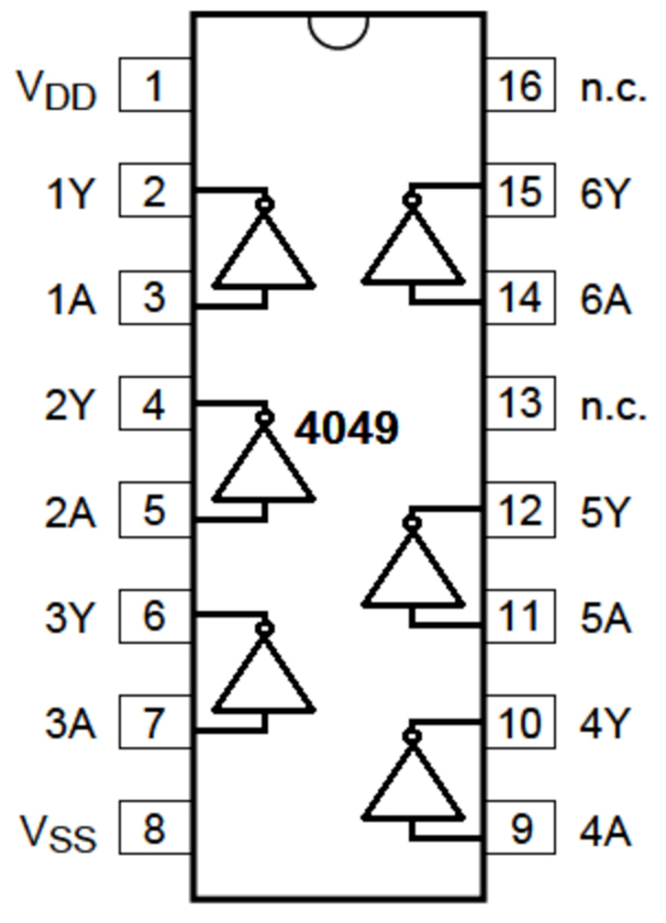
CD4049 Hex Inverter

I seemed to be cursed to "randomly" pick up hex inverters from the buckets and try to make unique circuits from them.

So far I have made an uninspiring but surprisingly popular blinker (CD4069), and a cool train crossing indicator (CD40106).

Fortunately I found another great circuit this time - using the CD4049.

The premise of the circuit is a "cupboard light" that uses minimal power until it is activated by a momentary switch, and then it shines only for a pre-determined amount of time.

It's a pretty cool idea and it worked really well, although the timing for the "on" part of the ciruit seemed a bit "off".

I didn't explore the discrepancy between calculated time and measured time - perhaps NOT tying down the other inputs caused the issue. Not that it was really a problem for me, I would just experimentally change the values until I had the time I needed.

I think a potentiometer for R1 might be "vary" useful to change these times as well.


Friday, October 28, 2022

0000 0000 1010 1101

Mailbag #23

What a wonderful grab bag of "wire critters" coming into Tassie this week.

Every packet opening a joy, and thank you to my Chinese suppliers for the mini rush of dopamine!

I have to say that the little semi-circular photo-transistor is my favourite in this bunch.


Wednesday, October 19, 2022

0000 0000 1010 1100

CH552G - Wunderkind?

Indulging my whimsical penchant for quirky tech I recently took delivery of the enigmatic CH552G. It turns out to have a lot of stuff locked up in its monolithic shell! From the datasheet comes the following:

  • Core: Enhanced E8051 core compatible with MCS51 command set, 79% of its commands are single-byte single-cycle commands, and the average command speed is 8 ~ 15 times faster than that of the standard MCS51, with special XRAM data fast copy command, and double DPTR pointers.

  • ROM: Non-volatile memory ROM that can be programmed for many times, with the capacity of 16KB, can albe used for program storage. Or it can be divided into a 14KB program storage area and a 2KB BootLoader/ISP program area.

  • DataFlash: 128-byte non-volatile data memory that can be erased for multiple times and supports rewrite data in unit of byte.

  • RAM: 256-byte internal iRAM, which can be used for fast temporary storage of data and stack. 1KB on-chip xRAM, which can be used for temporary storage of large amount of data and direct memory access (DMA).

  • USB: Built-in USB controller and USB transceiver, support USB-Device mode, support USB type-C master-slave detection, support USB 2.0 full-speed (12Mbps) and low-speed (1.5Mbps) traffic.

  • Support data packet of up to 64 bytes, built-in FIFO, and support DMA.

  • Timer: 3 sets of timers (T0/T1/T2), which are standard MCS51 timers.

  • Capture: Timer T2 is extended to support 2-channel signal capture.

  • PWM: 2 PWM outputs, PWM1 and PWM2, are 2-channel 8-bit PWM output.

  • UART: 2 sets of UARTs. Both support higher communication baud rate. UART0 is a standard MCS51 serial port.

  • SPI: The SPI controller has built-in FIFO, and the clock frequency can reach half of the system dominant frequency Fsys. It supports simplex multiplex of serial data input and output, and Master/Slave mode.

  • ADC: 4-channel 8-bit A/D converter. It supports voltage comparison.

  • Touch-key: 6-channel capacitance detection. It supports up to 15 touch keys, and supports independent timing interrupt.

  • GPIO: Up to 17 GPIO pins (including XI/XO and RST as well as USB signal pins).

  • Interrupt: It supports 14 sets of interrupt signal sources, including 6 sets of interrupts compatible with the standard MCS51 (INT0, T0, INT1, T1, UART0, T2), and 8 sets of extended interrupts (SPI0, TKEY, USB, ADC, UART1, PWMX, GPIO, WDOG). And GPIO interrupt can be selected from 7 pins.

  • Watch-Dog: 8-bit presettable watchdog timer WDOG, support timing interrupt.

  • Reset: 4 kinds of reset signal sources. Built-in power on reset, software reset, watchdog overflow reset and optional pin external input reset.

  • Clock: Built-in 24MHz clock source, which can support external crystals by multiplexing GPIO pins.

  • Power: Built-in 5V to 3.3V low dropout voltage regulator. It supports 5V or 3.3V or even 2.8V supply voltage. Support low-power sleep mode and external wake-up of USB, UART0, UART1, SPI0 and part of GPIOs.

  • Built-in unique ID.


The highlighted dot points above are particular features that I would like to explore with this little chip. The first of these (touch channels) is the subject of this blog and video.

In the diagram below any pins labelled TIN are touch channel pins.


The libraries/core files needed to program the device using the Arduino IDE can be accessed via a github site.  This includes a couple of examples using touch detection so I just borrowed my initial code from that repository.

I wanted to blink lights (of course!) when a touch was detected, but it becomes difficult if a light is blinking (and thus employing a pause or delay in processing) to detect a touch.

If we had, for instance, a blink of 1 second on, 1 second off the microcontroller is effectively "frozen" waiting for the delay to finish. A touch detection could be missed while the chip waits for this delay to be over.

This is a fairly normal programming dilemma for single core microcontrollers. As there is no multi-threading etc to split the program, I used a standard technique to simulate multi-tasking.

Effectively we let the clock keep running and the loop stays in motion. There are no delays used in the program to "pause" the instructions. Instead, we use timing markers and we do comparisons each time the loop is executed.

If a previously defined timer length is tripped, then something happens. For instance, if we are "waiting" one second for an LED to turn off, then a timer comparison between when the LED went on with the current time (an "if" statement with a subtraction) would trip that event.

There are plenty of good explanations for this method already online, and you could also step through the code provided below (and watch the video) to see how it is applied in this case.

/*
 * Touch PIN code for CH552G
 * OneCircuit Sat 24 Sep 2022 16:52:26 AEST
 */

#include <TouchKey.h>

// timing variables: how long since last touch, since
// last fast touch and since fast slow touch
long touchtime = 0;
long fast = 0;
long slow = 0;
long currenttime = 0;
int turnofftime = 15000; // no touch time, turn off LEDs

// were any wires touched?
boolean notouch = false;

// timing and status for LEDs
int slowtime = 500; // milliseconds
int fasttime = 100;
boolean slowstatus = false; // lit or not?
boolean faststatus = false;
boolean usingfast = false; // flashing fast or slow?
boolean usingslow = false;

// the led pins
#define LEDslow 30
#define LEDfast 11

void setup() {
  // output and write low
  pinMode(LEDslow, OUTPUT);
  pinMode(LEDfast, OUTPUT);
  digitalWrite(LEDfast, LOW);
  digitalWrite(LEDslow, LOW);

  // setup Touch key for TIN2 and TIN3
  delay(50);
  TouchKey_begin( (1 << 2) | (1 << 3) ); // Enable  TIN2(P1.4), TIN3(P1.5)
  delay(50);
}

// function that checks if wire has been touched
// then returns that wire
uint8_t checktouch() {
  uint8_t anytouch = 0;
  uint8_t stoptouch = 1;
  TouchKey_Process();
  anytouch = TouchKey_Get();
  
  // if you hold the wire, nothing happens until
  // you let go, even dousing the lights
  if (anytouch != 0) {
    digitalWrite(LEDfast, LOW);
    digitalWrite(LEDslow, LOW);
    while (stoptouch != 0) {
      TouchKey_Process();
      stoptouch = TouchKey_Get();
    }
  }

  return anytouch;
}

void loop() {

  // check if wires are touched and check
  // current time
  notouch = checktouch();
  currenttime = millis();

  // we've been touched, so turn on the appropriate LED
  if (notouch != 0) {
    touchtime = millis();  // start the timing count

    // it was a fast touch
    if ((notouch) & (1 << 2)) {
      usingfast = true;
      usingslow = false;
      digitalWrite(LEDfast, HIGH);
      digitalWrite(LEDslow, LOW);
      fast = millis();
      slowstatus = false;
      faststatus = true;
      notouch == 0;
    }

    // it was a slow touch
    if ((notouch) & (1 << 3)) {
      usingslow = true;
      usingfast = false;
      digitalWrite(LEDslow, HIGH);
      digitalWrite(LEDfast, LOW);
      slow = millis();
      faststatus = false;
      slowstatus = true;
      notouch = 0;
    }
  }

  // no touch so just check blinking time etc
  // are we past the turnoff time?
  if (currenttime - touchtime < turnofftime) {

    // fast led timing on and off
    if ((usingfast) &&  (currenttime - fast > fasttime)) {
      if (faststatus) {
        digitalWrite(LEDfast, LOW);
        fast = millis();
        faststatus = false;
      }
      else {
        digitalWrite(LEDfast, HIGH);
        fast = millis();
        faststatus = true;
      }
    }

    // slow led timing on and off
    if ((usingslow) &&  (currenttime - slow > slowtime)) {
      if (slowstatus) {
        digitalWrite(LEDslow, LOW);
        slow = millis();
        slowstatus = false;
      }
      else {
        digitalWrite(LEDslow, HIGH);
        slow = millis();
        slowstatus = true;
      }
    }
  }
  // past turn off time, so turn off everything
  else {
    digitalWrite(LEDfast, LOW);
    digitalWrite(LEDslow, LOW);
    slowstatus = false;
    faststatus = false;
  }

}

In the end the program worked out really well and due to the "fake multitasking" the pins were very responsive to touch.

I would be keen to implement interrupts as well and streamline the code a little bit.

I really enjoyed working with this little wonder, and soon I'll take a look at the "Built in unique ID" which seems interesting as well!


Friday, October 14, 2022

0000 0000 1010 1011

SuperCap II - the low low clock speed

"I'm always chasing rainbows!" - nice lyrics from Thomas Joseph McCarthy and in my case it could be better phrased as "I'm always chasing low clock speeds and energy requirements!"

It's a little fruitless and frustrating at times but I'm a big fan of Thomas Edison who said a couple of things that resonate in these strange pursuits:

1.  "Opportunity is missed by most people because it is dressed in overalls and looks like work.", and

2. "I have not failed 10,000 times. I have successfully found 10,000 ways that will not work."

So in this project the plan was to take a successful light design and change out the NiMH battery for a super-capacitor. The reason is that NiMH batteries have a much smaller cycle lifetime compared to super capacitors.

As well I want to wind down the clock speed on the Padauk PFS154 and see how low it can go. 

Also I will be using the 5050 Leds that I've used before to minimise the energy requirements.

The super-capacitor used in the last video was a "paltry" 4 Farads. The current version is 2x30 Farad capacitors, and I have some bigger ones coming - er, because see 2nd quote from Edison above!

The code side was where the big gains have been made - I was able to successfully wind down the clock to around 17000Hz (!) and still run the "candle".

/*
  Candle with Three PWM

  Pseudo-random flickering to simulate a candle. Output is
  via 3xPWM channels, variables can be changed to 
  alter the simulation

  Wed 12 Oct 2022 20:46:06 AEDT

*/

#include <stdint.h>
#include <stdlib.h>
#include "../device.h"
#include "../easy-pdk/calibrate.h"
#include "../auto_sysclock.h"
#include "../delay.h"
#include <stdbool.h>

#define LED4_BIT 4
#define LED0_BIT 0
#define LED3_BIT 3

uint16_t myrand = 2901;  // happy birthday

// global variables randomised later for flickering, using the
// "waveslow" and "wavefast" arrays
uint8_t slowcounter = 0;
uint8_t medcounter = 0;
uint8_t fastcounter = 0;
uint8_t slowstart = 0;
uint8_t slowend = 0;
uint8_t medstart = 0;
uint8_t medend = 0;
uint8_t faststart = 0;
uint8_t fastend = 0;
uint8_t faster = 0;

uint8_t waveslow[] = {50, 100, 170, 200}; // 1 leds on PA4
uint8_t wavemed[] = {40, 120, 140, 220};  // 1 led on PA3
uint8_t wavefast[] = {40, 80, 150, 240};  // 1 led on PA0

// booleans to keep track of "fading up" or "fading down"
// in each of the slow and fast cycles
bool fastup = true;
bool slowup = true;
bool medup = true;

void mydelay(uint8_t counter) {

  for (uint8_t thiscount = 0; thiscount <= counter; thiscount++) {
    _delay_us(1);
  }

}

uint16_t gimmerand(uint16_t small, uint16_t big) {
  myrand ^= (myrand << 13);
  myrand ^= (myrand >> 9);
  myrand ^= (myrand << 7);
  return abs(myrand) % 23 * (big - small) / 23 + small;
}

void getnewslow() {
  slowstart = gimmerand(waveslow[0], waveslow[1]);
  slowend = gimmerand(waveslow[2], waveslow[3]);
}

void getnewmed() {
  medstart = gimmerand(wavemed[0], wavemed[1]);
  medend = gimmerand(wavemed[2], wavemed[3]);
}

// initialise a new fast cycle including the new speed of cycle
void getnewfast() {
  faststart = gimmerand(wavefast[0], wavefast[1]);
  fastend = gimmerand(wavefast[2], wavefast[3]);
  faster =  gimmerand(1, 8);
}

// Main program
void main() {

  // Initialize hardware
  // Set LED as output (all pins are input by default)
  PAC |= (1 << LED4_BIT) | (1 << LED0_BIT) | (1 << LED3_BIT);

  PWMG1DTL = 0x00;                // Clear the LED PWM duty value
  PWMG1DTH = 0x00;
  PWMG1CUBL = 0xff; // set PWM counter upper bound to 0xffff
  PWMG1CUBH = 0xff;
  PWMG1C = 0x87;
  PWMG1S = 0b00000000; // prescaler=4, divider=1, no interrupt

  PWMG0DTL = 0x00;                // Clear the LED PWM duty value
  PWMG0DTH = 0x00;
  PWMG0CUBL = 0xff; // set PWM counter upper bound to 0xffff
  PWMG0CUBH = 0xff;
  // PWMG0C = (uint8_t)(PWMG0C_ENABLE | PWMG0C_INVERT_OUT | PWMG0C_OUT_PA0 | PWMG0C_CLK_IHRC);
  PWMG0C = 0x87;
  PWMG0S = 0b00000000; // prescaler=4, divider=1, no interrupt

  PWMG2DTL = 0x00;                // Clear the LED PWM duty value
  PWMG2DTH = 0x00;
  PWMG2CUBL = 0xff; // set PWM counter upper bound to 0xffff
  PWMG2CUBH = 0xff;
  PWMG2C = 0x87;
  PWMG2S = 0b00000000; // prescaler=4, divider=1, no interrupt

  getnewfast();
  getnewslow();
  getnewmed();
  slowcounter = slowstart;
  fastcounter = faststart;
  medcounter = medstart;

  // Main processing loop
  while (1) {

    // ramp up slow
    if (slowup) {
      slowcounter++;
      if (slowcounter > slowend) { // ramp finished so switch boolean
        slowup = !slowup;
      }
    }
    else {
      // ramp down slow
      slowcounter--;
      if (slowcounter < slowstart) { // ramp finished so switch boolean
        slowup = !slowup;
        getnewslow();
      }
    }

    // ramp up med
    if (medup) {
      medcounter++;
      if (medcounter > medend) { // ramp finished so switch boolean
        medup = !medup;
      }
    }
    else {
      // ramp down med
      medcounter--;
      if (medcounter < medstart) { // ramp finished so switch boolean
        medup = !medup;
        getnewmed();
      }
    }

    // ramp up fast
    if (fastup) {
      fastcounter = fastcounter + faster;
      if (fastcounter > fastend) { // ramp finished so switch boolean
        fastup = !fastup;
      }
    }
    else {
      // ramp down fast
      fastcounter = fastcounter - faster;
      if (fastcounter < faststart) { // ramp finished so switch boolean
        fastup = !fastup;
        getnewfast();
      }
    }
    // delay + a re-purposed random for ramp speeds
    mydelay(3+faster);

    PWMG1DTL = slowcounter & 255;
    PWMG1DTH = slowcounter;
    PWMG0DTL = fastcounter & 255;
    PWMG0DTH = fastcounter;
    PWMG2DTL = medcounter & 255;
    PWMG2DTH = medcounter;

  }
}

// Startup code - Setup/calibrate system clock
unsigned char _sdcc_external_startup(void) {

  // Initialize the system clock (CLKMD register) with the IHRC, ILRC, or EOSC clock source and correct divider.
  // The AUTO_INIT_SYSCLOCK() macro uses F_CPU (defined in the Makefile) to choose the IHRC or ILRC clock source and divider.
  // Alternatively, replace this with the more specific PDK_SET_SYSCLOCK(...) macro from pdk/sysclock.h
  
    PDK_SET_SYSCLOCK(SYSCLOCK_ILRC_DIV4);

  // Insert placeholder code to tell EasyPdkProg to calibrate the IHRC or ILRC internal oscillator.
  // The AUTO_CALIBRATE_SYSCLOCK(...) macro uses F_CPU (defined in the Makefile) to choose the IHRC or ILRC oscillator.
  // Alternatively, replace this with the more specific EASY_PDK_CALIBRATE_IHRC(...) or EASY_PDK_CALIBRATE_ILRC(...) macro from easy-pdk/calibrate.h
  
    EASY_PDK_CALIBRATE_ILRC(17000,3000);

  return 0;   // Return 0 to inform SDCC to continue with normal initialization.
}

Compiling was fine and oh so nice to have 2k available instead of the 1k ATTiny13 (although I am still keen to learn Padauk assembler and make this a bit smaller).

$> make program
sdcc -mpdk14 -c --std-sdcc11 --opt-code-size -DPFS154 -DF_CPU=1000000 -DTARGET_VDD_MV=3000 -I. -I../include -o .build/main.rel main.c
sdcc -mpdk14 --out-fmt-ihx -o .output/FadeLED_PFS154.ihx .build/main.rel .build/lib.lib
makebin -p .output/FadeLED_PFS154.ihx .output/FadeLED_PFS154.bin
---------- Segments ----------
.  .ABS.                            00000000    00000000 =           0. bytes (ABS,CON)
HEADER1                             00000000    00000002 =           2. bytes (ABS,CON)
HEADER3                             00000000    00000010 =          16. bytes (ABS,CON)
PREG2                               00000000    00000002 =           2. bytes (ABS,CON)
RSEG0                               00000000    00000002 =           2. bytes (ABS,CON)
DATA                                00000002    00000047 =          71. bytes (REL,CON)
HOME                                00000022    00000002 =           2. bytes (REL,CON)
GSINIT                              00000024    0000006C =         108. bytes (REL,CON)
SSEG                                0000004C    00000001 =           1. bytes (REL,CON)
GSFINAL                             00000090    00000002 =           2. bytes (REL,CON)
CODE                                00000092    000003E6 =         998. bytes (REL,CON)
------------------------------
Size of FadeLED_PFS154.bin: 1144 bytes
easypdkprog -i noblankchk -n PFS154 write .output/FadeLED_PFS154.ihx
Erasing IC... done.
Writing IC (572 words)... done.
Calibrating IC
* ILRC SYSCLK=17000Hz @ 3.00V ... calibration result: 16436Hz (0xF0)  done.

Left to do? Basically I want to keep on "Edisoning" this thing as follows:

a) Change the code to wind back the power of the ramping (e.g. instead of changing PWM from 40 to 220, try 30 to 160 or similar)

b) Upscale the super-caps. At the moment I'm getting around 4 hours of light - I think 6-8 hours is a reasonable goal.

c) Change some or all of the code from C to Assembler. This could be very scary given that assembler programming (which I love) is a pretty good path to madness.

d) Any suggestions??

Here's the video - enjoy!