// -----------------------------------------------------------------
// Description: A strip of Leds connected to a transistor controlled
// by an Attiny13. The μC sleeps most of the time, but is interrupted
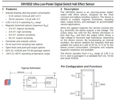
// by a PIR on PCINT1, or a Hall Effect sensor on PCINT2. It will then
// light the leds, hold for a bit and and then fade out.
//
// Author: OneCircuit      Date: Thursday 16 July 11:48:26 AEST 2020
// www.onecircuit.blogspot.com
// www.youtube.com/channel/UCTm3eCrN6wk-Ozt9ymyKIIg
// -----------------------------------------------------------------
//
// ATMEL ATTINY13 μC
//
//                                   +-\/-+
//  RESET--ACD0--5/A0--PCINT5--PB5  1|    |8  VCC
//   CLKI--ACD3--3/A3--PCINT3--PB3  2|    |7  PB2--PCINT2--2/A1--SCK--ADC1
//         ACD2--4/A2--PCINT4--PB4  3|    |6  PB1--PCINT1---1---MISO--OCOB--INT0*
//                             GND  4|    |5  PB0--PCINT0---0---MOSI--OCOA*
//                                   +----+
//  * indicates PWM port
//

#include <avr/pgmspace.h>            // for reading the progmem values
#include <avr/interrupt.h>           // for interrupt routines
#include <avr/sleep.h>               // the sleep routines

#define StripLED PB0                 // pwm pin
#define HEPin PCINT2                 // Magnetic interrupt pin
#define PIRPin PCINT1                // PIR interrupt pin

volatile boolean triggered = false;  // boolean for keeping track of interrupts

// The led strip will fade exponentially to compensate for human perception,
// which is not linear. You can calculate as a curve, but float values will blow
// the little Attiny13 out of the water, so a lookup table in progmem makes more
// sense for saving memory.

const uint8_t PROGMEM gamma8[] = {
  0, 0, 0, 0, 0, 0, 0, 1, 1, 1, 1, 1, 2, 2, 2, 3, 3, 3, 4, 4, 4,
  5, 5, 6, 6, 7, 8, 8, 9, 9, 10, 11, 11, 12, 13, 14, 14, 15,
  16, 17, 18, 19, 20, 21, 22, 23, 24, 25, 26, 27, 28, 29,
  30, 31, 32, 34, 35, 36, 37, 39, 40, 41, 43, 44, 46, 47,
  48, 50, 51, 53, 54, 56, 58, 59, 61, 63, 64, 66, 68, 69,
  71, 73, 75, 77, 78, 80, 82, 84, 86, 88, 90, 92, 94, 96,
  98, 100, 102, 105, 107, 109, 111, 113, 116, 118, 120,
  123, 125, 127, 130, 132, 134, 137, 139, 142, 144, 147,
  150, 152, 155, 157, 160, 163, 165, 168, 171, 174, 176,
  179, 182, 185, 188, 191, 194, 197, 200, 203, 206, 209,
  212, 215, 218, 221, 224, 227, 230, 234, 237, 240, 243, 247, 250
};

void slowfade(boolean fadein) {

  if (fadein) {
    for (uint8_t lighting = 0; lighting < 150; lighting++) {    // 150 steps
      analogWrite(StripLED, pgm_read_byte(&gamma8[lighting]));  // read from the lookup table
      delay(6);                                                 // increase for a slower fade
    }
  }
  else {
    for (uint8_t lighting = 150; lighting > 0; lighting--) {    // count backwards
      analogWrite(StripLED, pgm_read_byte(&gamma8[lighting]));  // from the lookup table
      delay(80);                                                // increase for a slower fade
    }
  }
}

void powerDown(void)
{
  GIMSK |= (1 << PCIE);                   // activate Pin change interrupts
  PCMSK |= ((1 << HEPin)|(1 << PIRPin));  // sets the Pin change interrupt mask
  ADCSRA &= ~(1 << ADEN);                 // turn off ADC
  ACSR |= (1 << ACD);                     // turn off Analog comparator.
  sei();                                  // enable global interrupts
  set_sleep_mode(SLEEP_MODE_PWR_DOWN);    // sleep deeply little one
  sleep_enable();                         // enable sleep mode
  sleep_mode();                           // system sleeps here

  sleep_disable();                        // ISR routine returns here so wake up
  GIMSK &= ~(1 << PCIE);                  // deactivate Pin change interrupts
  ADCSRA |= (1 << ADEN);                  // turn on ADC
  ACSR = (0 << ACD);                      // turn on Analog comparator.
  delay(100);                             // settle time after waking up

}

ISR(PCINT0_vect)
{
  triggered = true;
}

void setup ()
{
  pinMode(HEPin, INPUT_PULLUP);    // configure interrupt pin as input
  pinMode(PIRPin, INPUT_PULLUP);   // configure interrupt pin as input
  pinMode(StripLED, INPUT);        // LED pin input to start

}  // end of setup

void loop () {
  if (!triggered) {
    powerDown(); // call the function that sleeps
  }
  else {
    pinMode(StripLED, OUTPUT);    // LED pin is now output
    slowfade(true);               // fade in
    delay(60000);                 // hold that thought for 1 minute
    slowfade(false);              // fade out
    pinMode (StripLED, INPUT);    // configure transistor pin as input, saves power
    delay(1000);                  // one second before re-trigger
    triggered = false;            // reset boolean
  }
}  // end of code